Buoyancy
A subteam including Oscar Jopp, Kyle Goodwill, & Dennis Tanner
Concept Generation
The buoyant force of an object (assuming a fixed weight) depends on the volume of water displaced. In determining design ideas for the implementation of the robot’s buoyancy mechanism, several options were considered. Initially, we decided on the main and sub functions we wanted. The main functions we decided on were the capacity to move internal parts of the robot around to adjust balance, zone bladders which could change angle/balance robot, and lastly, a fail-safe mechanism to provide an optional boost to the buoyant force. The secondary functions included ideas such as the ability to attach an external floating device to other objects and dissipating heavier parts of the load, which later was deemed as non-ideal as harmful effects to the environment could occur.
Concept Selection

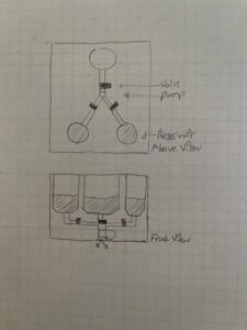
Focusing on the main functions, we narrowed down our options and chose the mechanism we would use to implement buoyancy control. We chose constant volume fluid reservoirs that we would adjust the amount of water inside of. We went with this design because it seemed to be the most mechanically feasible and reliable way to adjust the amount of water displaced. This design needs only to pump in/out water to/from its reservoirs to change the resulting buoyant force. It also consists of a pump and valve system that connects to three separate reservoirs. Each one can be filled separately, and this separation allows for balancing, compensating for any shifting weight in the robot.
In addition, we decided that a fail-safe mechanism was necessary. This is so that we can recover the robot in the event it cannot resurface through other means. Whether or not there is a control malfunction, the hydrostatic pressure is too great, or the robot gets snagged on something, this fail-safe mechanism should provide a dramatic boost in the buoyant force, ensuring the robot’s safety. A refillable CO2 cartridge and a deployable, inflatable float bag were chosen because they can displace a large amount of water relatively quickly and easily. We chose not to rely fully on CO2 for the main buoyancy feature in an attempt to mitigate the need for an external fuel source.
Concept Refinement
In determining the reservoir system’s size, the assumption for first iterations was that we were only testing in freshwater. This allowed for the relation of the magnitude of the buoyant force to the magnitude of freshwater weight. Specifically, the robot was modeled as weighing at most 40kg meaning we needed to at minimum displace 40N.
Wwater = WRobot
WRobot = m • g = (40kg)• (9.81 m/s2)
WRobot ≈ 400N
Utilizing the robot weight as 400N we wanted to displace 10% of that. This led to the reservoir volume being calculated on the idea that bilaterally symmetric reservoir placement was going to be implemented. Thus, we will have one reservoir on the front of the robot that will displace half of the 10% (20N) and two reservoirs in the back each displacing one fourth of the other half left (10N Each). Utilizing a cylinder reservoir we wanted to constrain the height and the wall thickness to L = 20.32cm and t = 0.3175cm. Allowing for the calculation of the reservoir volume to be changed solely off the inner radius. Additionally, we decided on an inner radius of 11.43cm for the front reservoir and 8.89cm for the two rear reservoirs.
VReservoir = πri2L
VReservoir,f ≈ 2100 cm3
VReservoir,r ≈ 1300 cm3
The above Volume was then multiplied by the density of freshwater, assumed to be ρ = 998 kg/m3 to get the total displacement that was appropriate of the 10% value of the robot’s weight; thus, effectively proving the volume displaced by the system is the correct size for the front reservoir as well as the two rear ones.
Df = VReservoir,f • ρ ≈ 21 N
Dr = VReservoir,r • ρ = 12 N (x2)
Thus, effectively showing that the reservoir system should allow for our robot to be neutrally buoyant achieving a displacement value greater than 40N!
