Treads, Wheels, & Leg Integration
A sub-team including Benjamin Gersten, Maddie Barto, & Keegan Martin
Concept Generation
Traditional legged robots require additional mechanical and digital complexity to ensure even basic functionality. By embracing the idea of hybrid designs, we at HARRT decided that using wheels and tracks as the end effectors of the robot’s legs enables heightened mobility with the bonus of increased project simplicity. This design choice allows us to focus our efforts on mechanical solutions that can readily be applied in the field as opposed to wrestling with monumental control systems. Wheels are a common design choice for many vehicles, providing high speeds, low maintenance costs. These would likely be used when operators anticipate somewhat standardized environments, including urban environments, grassy fields, well-maintained trails, and more. Treads and tracks, while somewhat more complicated, offer greater mobility over more complex surfaces, including sand, mud, rocky terrain, and more due to their increased surface area and reduced ground pressure. Using either type of end effector, when combined with legs, will enable the robot to clamber over larger obstacles, climb and descend stairs, and traverse small gaps, effectively fulfilling both the Land Movement and Climb and Scale Obstacles functions.
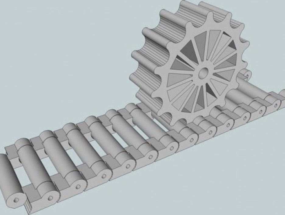
When considering designs for treads and wheels, we determined that the bulk of the design process would be focused on creating suitable tracks for the robot. Wheels are a readily available component that can be purchased, or, if need be, 3D printed with minimal complexity. By comparison, tracked vehicles require significantly more consideration, with heavily involved decisions regarding track width and surface geometry, sprocket design, suspension, and more. As such, we first began researching different track designs, using tanks as our primary source material, often referencing designs from the WWII era.
Simultaneously, we engaged in constant discussion with the Legs sub-team as our primary constraint was that, regardless of the type of system we create, it must fit within the geometry that the Legs team dictates. Together, the teams discussed designs that involved entirely detachable drive assemblies, where a modular tread system would “clip” onto the legs and receive power from the chassis, “forked” ends to the leg, where each side of the fork would extend to support both sides of the wheel/track, cantilever mounts, where the leg would act as a solid body with the wheel/track attached outside it, and hybrid wheel-track designs, where the wheels would be designed such that they could function simultaneously as standard wheels and sprockets or pseudo-drive wheels for the tracks. Other conversations discussed internally powering the wheels and tracks via motors inserted into the wheel body or track support structure versus externally powering the wheels and tracks via motors housed in the lower leg segment.
Concept Selection
The next step of the design process includes distilling the numerous design concepts generated during the ideation phase into one or two designs to eventually refine.
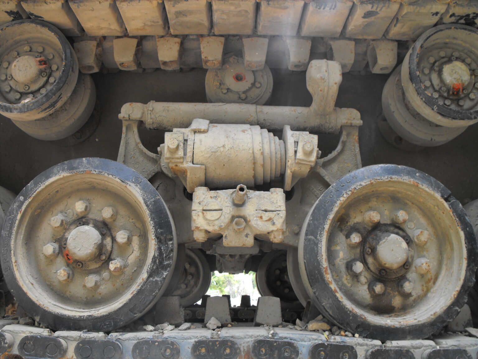
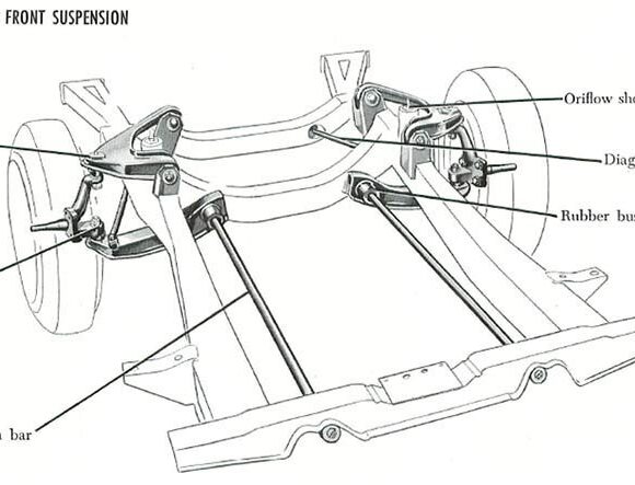
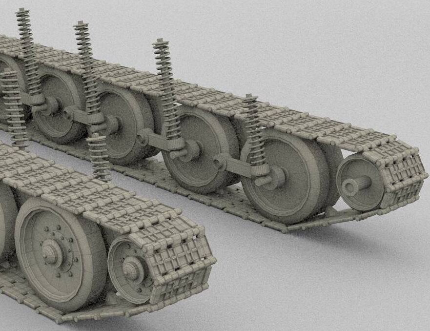
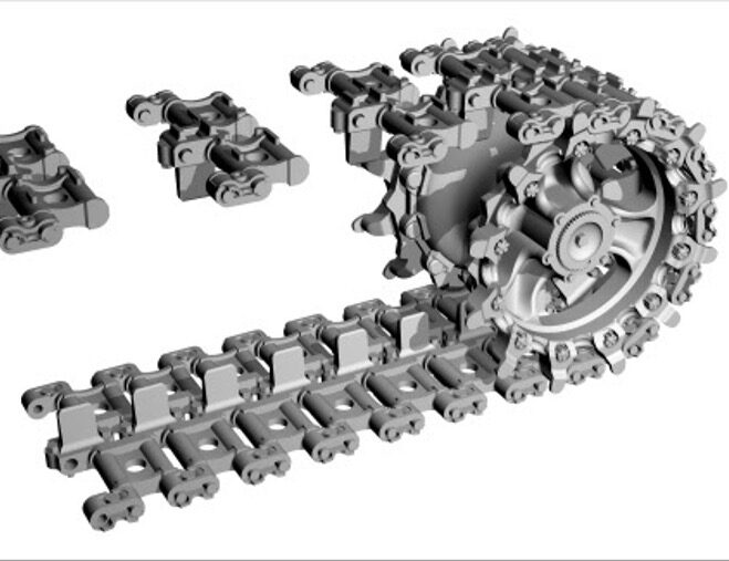
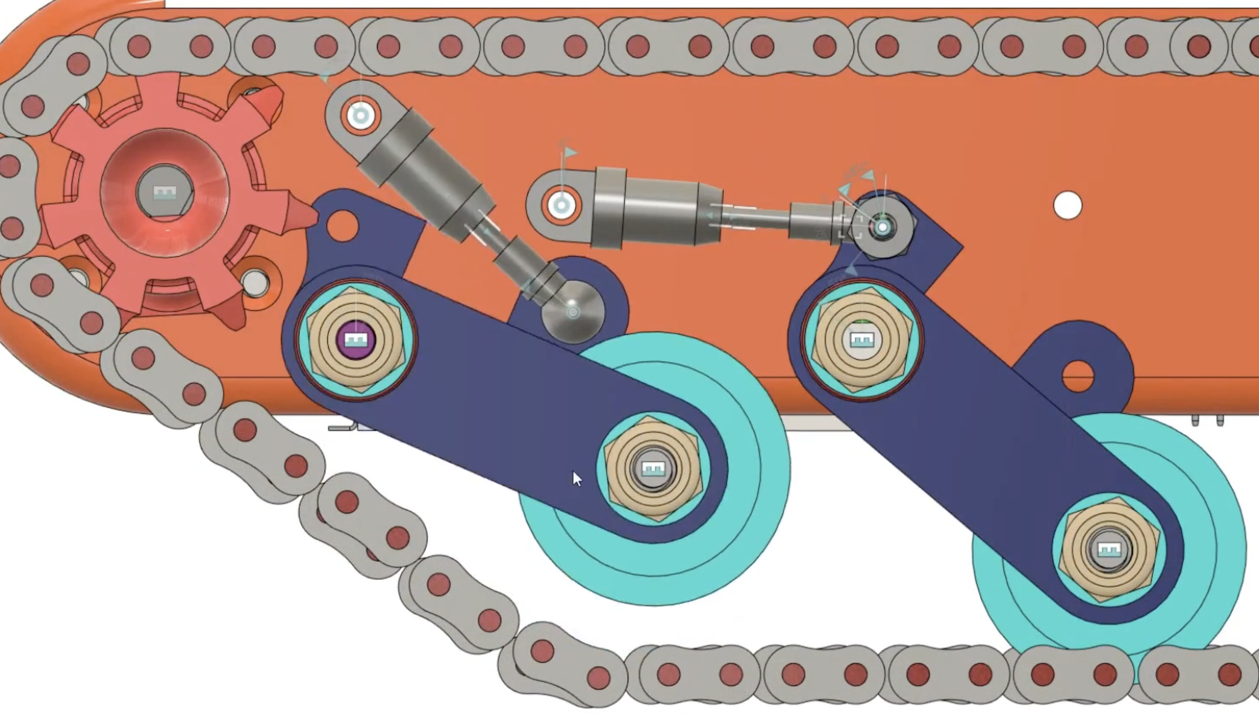
Regarding the treads, we decided to pursue a D-type shape track for its common usage in military vehicles, lending us confidence in its design features. We believe that the D-type track offers good obstacle traversal in the forwards and reverse directions while maintaining a largely symmetrical and well-understood form, reducing design complexity. This subsequently led to the selection of the Christie suspension system. Research had shown that the Bogie/HVVS system, while known for its modularity, was extremely bulky and possessed limitations in its maximum loading capacity for a given bogie size. Similarly, although torsion bars are used on many modern tanks due to their balance of mechanical simplicity and design effectiveness, the nature of our robot being legged makes this type of suspension physically unreasonable. One of the primary decisions to use legs was to elevate the robot’s ability to maneuver over complex obstacles, in part by raising itself and increasing its ground clearance. Since torsion bars in tanks conventionally run transversely through the tank’s body, this would effectively reduce any ground clearance our robot might gain to that of a typical car. Torsion bars can be mounted longitudinally, as shown in a slideshow earlier, however, tracked systems benefit from a large number of road/roller wheels, which provide support to the track. Each wheel gets its own suspension; implementing this in a tracked system would require the overlapping of torsion bars horizontally and vertically, drastically increasing track complexity and height. As such, the Christie suspension was selected almost by default. However, we found that various hobbyists and modern designers had found ways to overcome the Christie suspension’s old drawbacks (namely that they consume a large portion of the internal space of a tank). The resulting concepts we selected for the tank tracks are based on designs from such hobbyists, shown below.
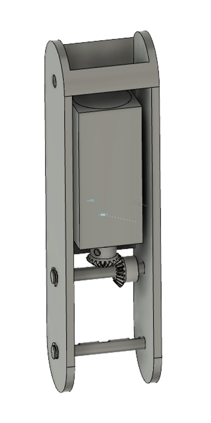
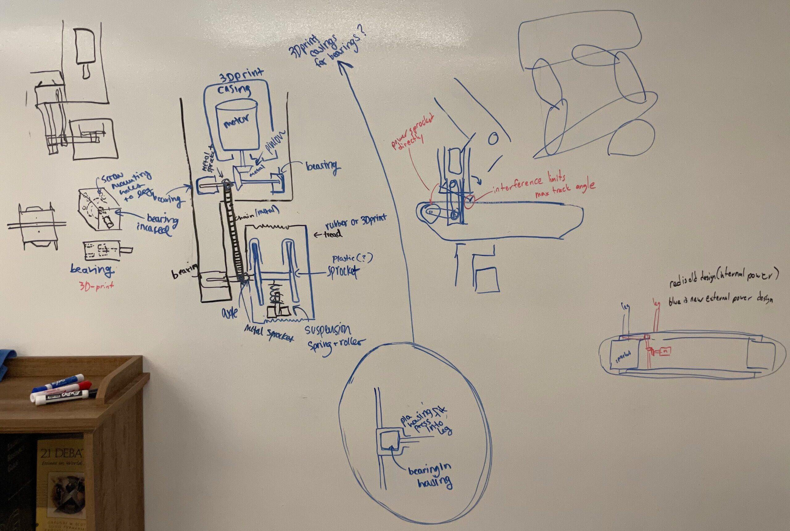
With respect to integration with the legs subteam, we decided to use some form of a fork and “clip-on” assembly. In this design, the wheel would fit inside the fork of the leg, mounted on an axle between each side of the fork. Structurally, the forked design allows for balanced forces when using the wheels by keeping the wheels in line with the rest of the leg and by providing equal support on either side, reducing the impact of bending moments. To allow for increased track width, the tracks would be mounted on an extended shaft through the same location such that they rest cantilevered on the outside of the leg. This extended shaft would be only added if the tracks were determined as needed by the operator. While the decision to have separate tracks and wheels that rest almost adjacent to each other consumes more space than a wheel-sprocket hybrid, it does offer some benefits. Primarily, a wheel-sprocket design would not allow for the full range of motion for the leg that is desired due to geometric interference from the fork. Likewise, it was decided that this hybrid wheel-sprocket design would make too many sacrifices to the effectiveness of separate wheels and tracks.
Determining how to power the wheels and tracks also naturally led to the selection of a single general design decision. Consulting our faculty advisor, we determined that powering wheels using internal motors would provide significant waterproofing challenges, and discrete motors housed within the attachable track system would dramatically increase weight and cost. Consequentially, we decided to house the motor inside the lower leg segment, using it to provide power to both the wheel and tracks, whichever are attached at a given moment.
Concept Refinement
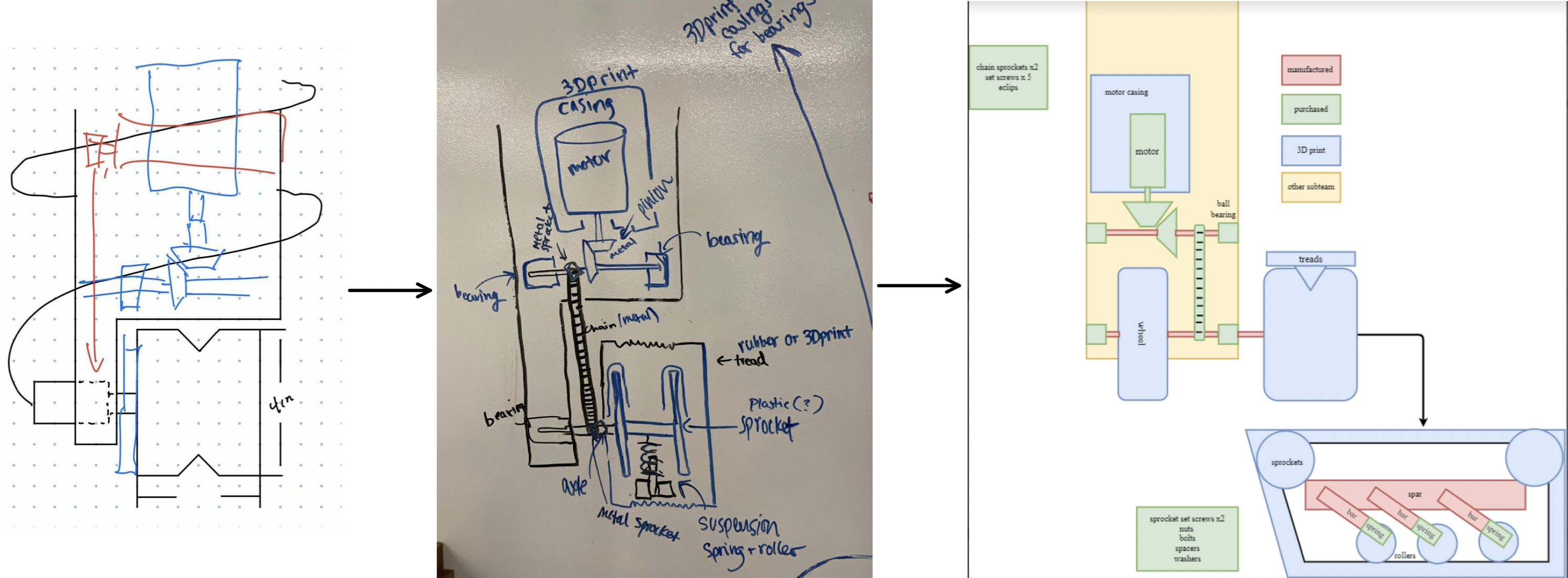
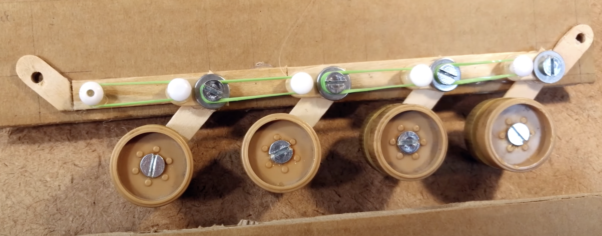
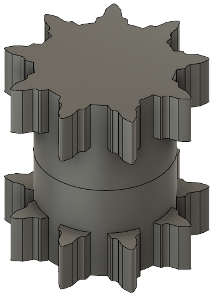
After selecting our design concepts, we began the process of refining them, thus beginning a cycle of adding detail, discovering new questions, and performing more research. In our sub-team, we elected to continue adding detail via “pencil and paper” before moving on to more advanced CAD models. This allowed us to remain agile with our design decisions as it is far easier to make small and repeated changes to even more detailed conceptual drawings than to CAD models. An example of this process can be found above with the progression of our designs for the integration with the Legs sub-team. We took deliberate steps to consider manufacturing costs and feasibility at all points of the design, thus influencing our selection of which parts to buy, manufacture, or 3D print. For example, motors, gears, and chains are complex components that must be purchased, while wheels and sprockets would benefit from the flexibility and rapid production time of 3D printing. Similarly, the shafts and axles for the wheels along with the structural spar and suspension system for the tracks are structural components that require high strength, thus necessitating them to be custom manufactured. While suspension systems are reasonably complex systems, we elected to custom make all of our Christie suspension systems as using components from RC cars and tanks would significantly constrain the size and weight of our robot.
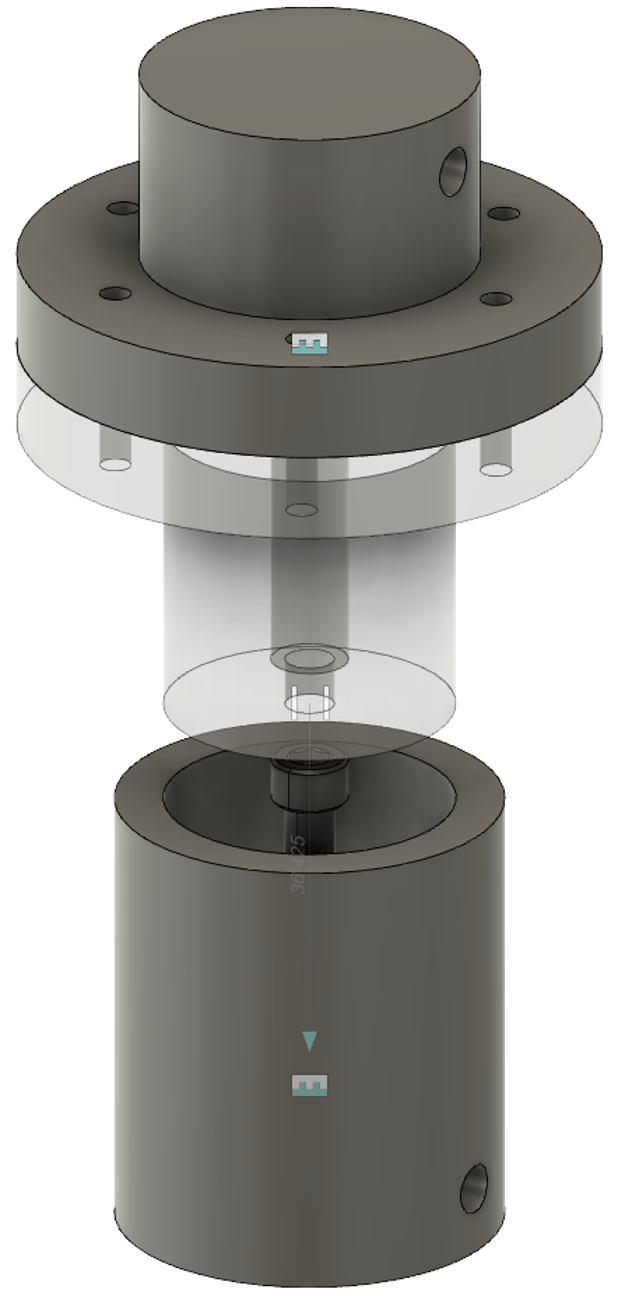
| Upon reaching a satisfactory level of detail with our conceptual drawings, including component part types and materials, we began working on our mid-to-high fidelity CAD models. Some of our current progress is shown to the right. When constructing these CAD models, we utilize our prior research in potential part acquisition as well as our initial investigations into material types and constraints to inform our decisions. One core aspect our design has centered around is the dimensions of the motor we have selected for the drive system, a brushless DC motor with a planetary gearbox that can run using 24V at 430RPM with a stall torque of around 1.7 Nm. We selected this motor due to a balance of cost, dimensions, and the necessary torque we determined necessary to move up a 40˚ incline (calculations in the appendix).
Further exemplifying the level of scrutiny we apply to our designs, our track system has been designed to utilize consistent screw sizes for multiple purposes. In the suspension-spring column, we have selected #10 screws to act as the anchors to the spar and roller wheel mounting bracket as well as the plunger for the column itself. The high availability of these screws and their relative strength for the size of our robot helps simplify our design as we can easily implement identical parts across the robot without the need to frequently reference diagrams of sub-system-specific components and specifications. Further, the suspension column has been designed such that only a lathe and drill press/mill are required to manufacture, reducing tooling time and manufacturing complexity. |
See some of our first semester accomplishments here!
Some of our final work here:
Appendix:
Calculation of torque necessary for a 40˚ incline:
Citations:
- Allpar.com Content. (2020, November 16). Chrysler Torsion Bar Car Suspensions, 1957-1992: Torsion-Aire, Torsion-Quiet. Allpar Forums. Retrieved October 20, 2021, from https://www.allpar.com/threads/chrysler-torsion-bar-car-suspensions-1957-1992-torsion-aire-torsion-quiet.229918/
- Curious Crafter. (2018, September 22). DIY Tank & Suspension tutorial. YouTube. Retrieved October 20, 2021, from https://www.youtube.com/watch?v=8mnYK_0FPFc&t=1s
- Don Busack Consulting. (n.d.). M50 Suspension System HVSS Walk Around Page 3. Prime Portal. Retrieved October 20, 2021, from http://www.primeportal.net/tanks/anon_idf/m50_suspension_system_hvss/index.php?Page=3
- Engineering Juice. (2020, December 30). How I made a tank suspension in fusion 360! YouTube. Retrieved October 20, 2021, from https://www.youtube.com/watch?v=NlmCbyYkuyY
- Enigma. (2011, April 13). Robotic tracks / treads. Legos Make the World Go Round. Retrieved October 20, 2021, from http://simpleengineering.blogspot.com/2011/04/robotic-tracks-treads.html
- Olimp Resin Accessories. (2018, January 8). Olimp resin accessories -35-01 update set tracks and drive Sprockets for Soviet main battle tank T-64 A/b/BV/BM2/U. Super-Hobby. Retrieved December 20, 2021, from https://www.super-hobby.com/products/Update-set-Tracks-and-Drive-Sprockets-for-Soviet-Main-Battle-Tank-T-64-A-B-BV-BM2-U.html
- Tanks. Being tanks. (2017, June 1). The Christie suspension is a suspension system developed by the American Engineer… Facebook. Retrieved October 20, 2021, from https://www.facebook.com/tanksbeingtanks/posts/the-christie-suspension-is-a-suspension-system-developed-by-the-american-enginee/1508010615924345/
- “tank tread” 3D models to print – yeggi – page 6. yeggi. (n.d.). Retrieved December 20, 2021, from https://www.yeggi.com/q/tank+tread/6/


