Legs Design & Chassis Integration
A subteam including Will Murphy, Jem Baker, & José Pincay
Concept Generation
While the legs are meant to provide the infrastructure for walking, this won’t be implemented by us. In looking for inspiration, we came across the Hyundai Tiger, which is a robot that drives on four-legged wheels with multiple joints and degrees of freedom on each one. The Tiger served as a starting point for our design, especially the shape of the upper leg and the means of folding efficiently. The folding of the legs will allow the robot to change its level of clearance while moving on land and to greatly reduce drag while traveling underwater.
Concept Selection
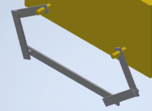
The major decisions of the legs came down to the degrees of freedom and number of joints; a four-legged design had been decided on as the simplest and most effective earlier. Guided by biomimicry, we decided on two joints. The degrees of freedom (number of rotational axes) was a harder debate: we decided on only one at the “knee” early on, but there was a debate on having two at the “hip,” where the leg connects to the chassis. Two would allow us to splay the legs, like raising an arm out to the side as well as swinging it forward and back, but this would add a lot of weight and complication, not to mention an additional strain on the budget. It was decided that one degree of freedom would be enough for the hip as well. This gave us the tools for a simplistic “popsicle stick” model, made in Inventor, to visualize the articulation of the legs with the rigid treads connecting them.

Concept Refinement
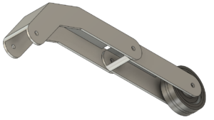
The shape of the legs needed to be refined from the basic popsicle stick model. We adapted the upper leg of the Tiger, which has two bends, for wheels of the size we desired to fit into when folded. Since the electronic systems will have to be waterproofed, the legs were made three-dimensional, allowing room for motors, sensors, and wiring within the profile of the leg. The lower leg is a simple straight box design that can fit motors that drive the wheels/treads, and the motor that drives the knee will be enclosed in the upper leg.

The choice of the motor was a difficult process. Many RC motors are made to spin very fast and output very little torque, which is the opposite of what the robot’s legs require. The motors found for the lower leg are made to work at 124 RPM with a rated torque of about 3 Nm; working with a 40 kg robot, we need 30 Nm of torque so we will implement a 10:1 gear ratio as well. This will enable the robot to fold and unfold in a couple of seconds, which is reasonable. Similar motors will be used for the hip, and these will be housed inside the chassis.
