Prototyping
In our journey to develop our robot, each sub-team has produced several prototypes. These manifestations of our designs helped inform our design decisions, project planning, and scope re-assessment. Many of these prototypes are the result of numerous iterations, broken down at smaller levels for problem-solving before handling higher-level integration.
Legs
The legs team produced several prototypes over the two semesters, each with improvements over the last iteration.
Fall 2021 Iteration:
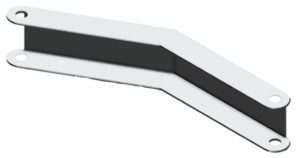
The very first prototype was a simple half scale 3D printed model just to get the team thinking about how to integrate the legs with treads/wheels and fit power systems within it. The team had done research into existing vehicles with wheels and legs and liked the Hyundai Tiger, so HARRT’s legs were loosely based on the Tiger’s bent legs with high folding capacity.
February 2022 Iteration:
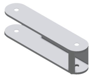
In February, the team printed the first full scale model of the leg; the upper leg had to be printed in two halves which were glued together. The upper leg has an axle-to-axle length of 30 cm, while that of the lower leg is 18 cm. The lower leg underwent minor revisions, including the move to a more closed design than the 2021 iteration, with more room made for the wheels’ power system as well as gearing and hub mounts. The leg now had space for motors and gearing, as well as a more contoured shape to reduce some stress concentrating features of the previous geometry and improve aesthetics.
May 2022 Iteration:
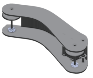
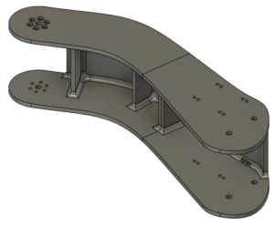
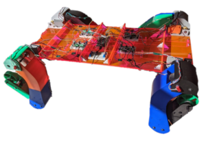
The final iteration of the leg included ribs for the upper leg to strengthen it, including a rib twice as thick as the others where the two halves were to be bonded, allowing for a bolted joint, well as a larger surface area for hot glue as a secondary measure. The upper leg was also made wider to accommodate changes to the lower leg and knee joint. The team designed and fabricated a chassis made of acrylic and chassis mounts for each leg were printed as well. The final step was adding the controller, and Arduino, and all the necessary wiring for motors, angle sensors, and potentiometers.
Treads/Wheels
Fall 2021 Iteration:
At the end of the Fall 2021 Semester, the progress and focus of the Treads/Wheels (TW) sub-team was largely on laying the proper groundwork for the next semester. The sub-team had worked extensively with the Legs sub-team to discuss a design for the entire Land Movement assembly that both teams could agree upon. As such, extensive work was done on anticipating and remediating the main interfaces between the two subsystems. This returned a finalized conceptual design for both groups. The conceptual design for the Legs subsystem is present in the previous section. The TW sub-team decided to encase the drive motor for the assembly in the lower leg and use a gear and pulley train to transfer power to the drive interfaces. Calculations were done for the appropriate motor based on the approximate size and weight of the robot. Given the focus on integration, some compromises needed to be made to make viable the goals of both sub-teams. In turn, this lead to a design which included the track assembly being placed external to the lower leg. This would allow for the legs to fold within themselves, without interference of the track. However, this also lead to certain anticipated issues, primarily over the frictional force that would result from having the shaft cantilevered with the full weight of the tracks freely hanging on one side. Nonetheless, this was determined as the design moving forward and other design choices that decrease friction and not affect the Leg’s assembly were made.
February 2022 Iteration:
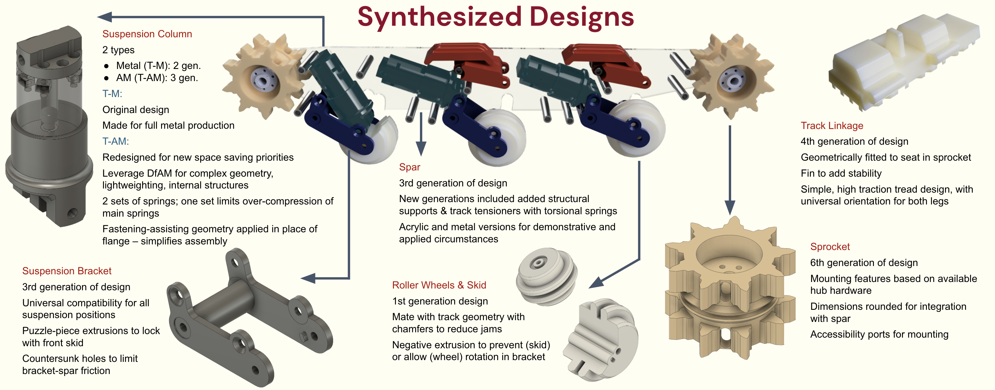
At the beginning of the Spring 2022 Semester, the state of the TW subsystem had progressed significantly from the end of Fall 2021 Iteration. The major progress came in the form of transitioning from a largely conceptual design, to viable CAD designs and physical components. The major accomplishments that marked the beginning of the semester were the completion of the suspension columns and sprocket design and the design and manufacturing of multiple components for the lower leg drive assembly. Additionally, a full scale model of the lower leg was printed and given for revision to the Legs sub-team.
May 2022 Iteration:
The final poster presentation saw the completion of the TW subsystem and full integration with the Legs subsystem. Much of the design of the final product was guided and improved by testing done throughout the second semester. The major tests and their ensuing design adaptions are as follows:
Drive assembly – it was found the motor housing was ineffective in its initial form in containing and holding in place the motor when the motor was driven at higher voltages. As such, the housing was reinforced and slots were designed into the lower leg to better locate the housing.
Treads – initially the interface between each of the individual tread links was temporarily accomplished using modified paper clips. While this was effective in completing the task of affixing the links to one another, it allowed for too much slack in the track and side-to-side movement. As such, the track linkages were modified post print to accept 2 mm rod that was press fit in. This provide a much tighter tolerance and better final product.
Spar – the spar underwent many improvements from its initial design, although most improvements were anticipated and planned for. The initial spar design consisted of two acrylic sheets that contained mounting holes for the suspension components. Upon full assembly in that state, it was found that the spar flexed too much under the tension of the track loop, that there was significant friction on the shaft holes, and that the structure was not rigid without tightening the suspension bolts, thereby locking up the suspension. Each of the problems was fixed with the following improvements: the acrylic spars were replaced with aluminum sheets of the same thickness, bearing holes were made which significantly reduced friction in the spar, and 50 mm spacers were added throughout the free space between the spar sides to increase rigidity. Additionally, track tensioners were added to the top of the spar to align the track when the lower suspension was fully compressed.
Development process
Buoyancy
Throughout the past two semesters, the Buoyancy sub-team generated several prototypes, each of which had varying dimensions and was more efficient at ascending/descending as well as maintaining a flat orientation in water.
Fall 2021 Iteration
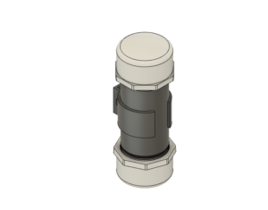
The first Reservoir prototype was generated November / December 2021. This included the initial design of three Reservoirs in a triangular placement (one at the front and two at back of chassis) that would be 4” in length with an inner diameter of 1.939” controlled by one peristaltic pump. Additionally, the first iteration of the Reservoir Holder and PVC end cap were designed and can be seen below:
March 2022 Iteration
This iteration of the Reservoir redesign increased the size of the reservoirs from 4” to 6” while keeping the inner diameter the same from Fall 2021. The reservoir redesign also included adding a fourth reservoir and three more peristaltic pumps to assure that the robot would be able to ascend and descend in the water properly as discussion had begun with the Swim sub-team. Additionally, the Reservoir Holder was redesigned to ensure the Reservoir would not slip from the holder.
May 2022 Iteration
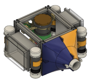
Upon more discussion with the Swim sub-team the works of an open water chassis design was created. This included a T-slotted aluminum metal chassis that could then be mounted onto, and reshaping and placing the reservoirs to allow for Swim sub-team to have access to the middle of the chassis. Additionally, sensors to measure the outside hydrostatic pressure and reservoir fluid capacity were implemented via a control system. The final synthesized design at the Level 2 standard can be seen below:
Propulsion
Throughout the past 2 semesters, the Swim sub-team generated several prototypes, each of which had varying dimensions and was more efficient at propelling water.
Fall 2021 Iteration:
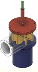
The first Centrifugal Pump prototype was generated in December of 2021. This was the largest prototype generated, with the least efficient water propulsion mechanism. The inlet and outlet diameter were 0.07 m and 0.05 m, respectively. Additionally, the casing diameter was set to 0.07 m and the casing height was set to 0.09 m. The CAD model for this initial prototype can be seen below.
March 2022 Iteration:
This iteration of the Centrifugal Pump prototype was similar to that generated in Fall 2021. However, at this point in time, size discussions were in the works with the Buoyancy sub-team. Therefore, while the design was similar to the prototype that was previously generated, the size was on a much smaller scale. Specifically, the inlet and outlet diameter were 0.03 m and 0.02 m, respectively. Additionally, the casing diameter was 0.045 m and the casing height was 0.035 m.
May 2022 Iteration:
This final prototype included changes to the CAD design to improve the efficiency of the design. Specifically, an angled cone design was added to the outlet pipe to increase the speed at which water exits the pump. A cone design was also added to the impeller to produce relatively small tip clearance. The inlet and outlet diameter of the prototype was 0.06 m and 0.035 m, respectively. The casing height was 0.08 m and the casing diameter was 0.06 m. Moving on, the Swim sub-team conducted research on waterproofing mechanisms for the prototype. The team chose to purchase a Bilge Pump with an already-sealed motor, given the challenges of waterproofing in the limited time frame that we had. Therefore, the new prototype design included a casing cover and impeller that would house the motor. Our final Centrifugal Pump CAD model can be seen below.
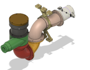
In terms of integration with the Buoyancy sub-team, the final Water Movement prototype included a ring design to house the Centrifugal Pump onto the inner chassis. The ring design can be seen, as part of the pump CAD design above.

