Prototype Specifications Deliverable
Mobility
| Priority | Specification | Lower Bound | Upper Bound | Units |
| 1 | Break Time | 0 | 60 | Seconds |
| 2 | Torque | 4 | 50 | Pound-feet |
| 3 | Velocity | 10 | 15 | mph |
| 4 | Weight | 2 | 10 | lbs |
| 5 | Cost | 200 | 1000 | $ |
Requirements:
The battle-bot’s mobility system is primarily constrained by the rules set forth by the NHRL. These rules include a break time of 60 seconds, which we hope to minimize for safety purposes. If this specification is not met, we will not be eligible for competition. Weight is another specification by the NHRL. The entire bot must have a maximum of 30 pounds, so we allotted a maximum of 10 pounds to the mobility subsystem. This system would ideally be minimized, but we are focused on the motors’ torque and velocity to ensure success in battle. As such, weight may need to be a small sacrifice for torque and velocity. Cost is also a limiting factor as the department will only grant us a certain amount of money for our project.
Mobility Motors
| Priority | Specification | Lower Bound | Upper Bound | Units |
| 1 | Delivery Date | 0 | 28 | Days |
| 2 | Weight | .25 | 1 | lb |
| 3 | Power | 500 | 2000 | W |
| 4 | Mounting faces | 1 | 2 | # |
| 5 | Total Length | .25 | 3.6 | in |
| 6 | Radius | .25 | 2.5 | in |
| 7 | Cost (each) | 10 | 100 | $ |
Requirements:
In our system, motors were granted a maximum of 1 lb total, but that was a value we hoped to minimize. The power to the motors had to be compatible with our batteries, so the ultimate target was 1600 W. The number of mounting faces was significant so that we had a way of permanently fixing the motor inside the robot. The size of the motors was also significant as they needed to fit within the main body as soundly as possible. These were values we also hoped to minimize. Ultimately, we need to build this robot as quickly as possible, so speedy delivery became a very high priority, and we refused to order a motor if the delivery time was too long.
Mobility ESC
| Priority | Specification | Lower Bound | Upper Bound | Units |
| 1 | Delivery Speed | 0 | 28 | days |
| 2 | Amperage Rating | 50 | 160 | amps |
| 3 | Reversibility Percentage | 0 | 100 | % |
| 4 | Cost | 5 | 20 | $ |
Requirements:
Delivery speed was also a large concern with the ESC’s. The amperage rating was of significant value, because it needed to be able to handle the current of the system. Reversibility and breaking were two additional factors that weighed into the ESC selection, as they were necessities in our robot design, but they are not necessarily metrics. Cost also weighed in, but ESC’s are not likely to take a large chunk of the budget.
Batteries
| Priority | Specification | Lower Bound | Upper Bound | Units |
| 1 | Cells | 3 | 8 | S |
| 2 | Weight | 0.5 | 6 | lbs |
Requirements:
A large percentage of the mobility weight was attributed to batteries as we wanted to maximize the energy storage capability. Our target battery cells value was 5S with a minimum of 3 and a maximum of 8 as that was the most compatible with our motor and ESC selection.
Mobility Gearbox
| Priority | Specification | Lower Bound | Upper Bound | Units |
| 1 | Can handle x lbs of force | 44.79 | ∞ | lbf |
| 2 | Profile Area | .25 | 15 | in^2 |
| 3 | Length | .25 | 2.5 | in |
| 4 | Gear Ratio | 4.65:1 | 6.2:1 | |
| 5 | Max Torque | 1.8 | ∞ | lb/ft |
| 6 | Max RPM | 43 | ∞ | RPM |
| 7 | Weight | 0 | 2 | lbs |
| 8 | Material Hardness | 15 | ∞ | Brinnell |
Requirements:
In finding a gearbox, the primary factor was the amount of force it was capable of rotating, as it would be the weak point in the mobility system. Furthermore, the profile area and length are significant as it will likely take up a large amount of space within the robot frame, so we hope to minimize this value. The target gear ratio for our system was calculated to be 4.8:1, with a lower bound of 4.65:1 and an upper bound of 6.2:1. Our minimum maximum torque was calculated to be 1.8 lb/ft and our minimum maximum RPM was calculated to be 43. We aim to maximize both of these values. The weight of the gearbox must be less than two pounds, but that was found to be very possible. We would also like to maximize the material hardness with a minimum maximum of 15 on the brinell scale.
Attack
| Priority | Specification | Lower Bound | Upper Bound | Units |
| 1 | Shutdown Time | 5 | 60 | Seconds |
| 2 | Withstand Time | 0 | 0.25 | Seconds |
| 3 | Rotational acceleration | 1 | 2 | rad/ s^2 |
| 4 | Rotational Velocity | 1 | ∞ | Rad / s |
| 5 | Weapon Energy Storage | 1000 | ∞ | Joules |
| 6 | Cost | 500 | 750 | $ |
| 7 | Bite size | 1 | 2 | cm |
| 8 | Weight | 4 | 6 | lbs |
Components:
Spinner and Spinner Support :
Requirements:
The attack system would be a vertical spinner that would be capable of delivering large amounts of damage to other robots. The attack system must be strong enough to withstand impacts. The attack system must not damage the motor when it impacts with an object and abruptly stops. The spinner must be able to maintain a stable rotation in addition to not being damaged when impacting objects.
Our design:
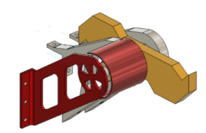
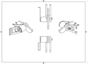
Specifications:
Our design utilizes a vertical spinner that is on on ⅕ in axle. This axel is supported by two bearings. These bearings are supported within two support arms that are ½” aluminum. In order to properly support the spinner the mounting arms would be secured to both the front of the battle robot and the top. In order to prevent the drive system from being damaged there are 2 protective plates. The protective plates are ⅛” aluminum, one of which is secured on the support arm and the other is secured to the main body of the battle robot. The main weapon is made of ½” steel and would be secured to the axle using a key slot. The shape of the spinner is designed to increase the moment of interior of the spinner and increase the “bite” ability of the spinner.
Front supports:
Requirements:
The front supports must be capable of withstanding reaction forces created by the weapon system when impacting objects. The furthest point of the front support must reach past the point of rotation of the spinner. The purpose of the front supports is making sure the robot does not flip over when impacted.
Our design:
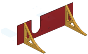
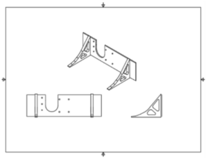
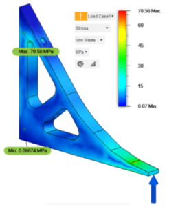
Specifications:
Our design for the front supports are ½” aluminum that is designed to extend in front of the spinner. The front supports will be manufactured with a water jet cutter, removing excess material to reduce the weight. The front support will attach to the front of the battle robot.
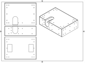
Defense
Sub Frame :
Requirements:
The subframe from the battle robot is the skeleton that supports all other subsystems. The Subframe must contain mounting locations for internal and external components. The subframe should weigh less than 6 lbs. The dimensions of the subframe will house the wheels and all the interior components of the battle robot.
Our design:
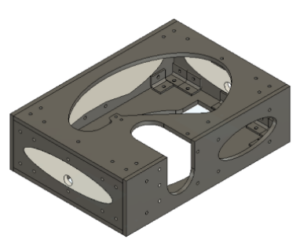
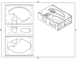
Specifications:
The subframe is designed with .25 in aluminum. The design consists of 6 panels that will be manufactured with a water jet cutter. The 6 panels are connected with steel L brackets. Portions of the panels were removed to reduce the weight of the subframe. In order to maintain the structural integrity, a .25 thick piece of plastic is manufactured to fit into the negative space in the rear and side panels. Upon impact, the subframe is likely to deform, so by filling the holes with plastic, deformation is minimized. The panels are overlapped, so the weakest point being the real panel is supported by the side and top panels, and the top panel is supported by the side panels. The subframe has an opening for the spinner’s drive system. The subframe is also reinforced in the front where the spinner supports are connected.
External Shielding:
Requirements:
The external shield needs to serve the purpose of providing additional protection to the battle robot while maintaining a low weight and securing the subframe. The external shield should also have connecting points for external components. There should also be an opening for the weapons drivetrain and the wheels.
Our design:
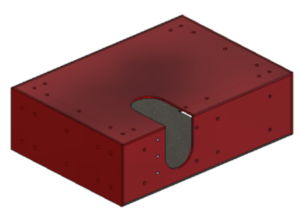
Specifications:
Our external armor consists of aluminum plates that are 0.125” thick.
# |
Specification |
Relevant Subsystem |
Min, Max, or Target |
Lower Bound |
Upper Bound |
Units |
| 1 | Weight | General | Min | 0 | 30 | lbs |
| 2 | Size X*X*X | General | Min | 0 | 36 | in |
| 3 | Cost | General | Min | 0 | 3500 | $ |
| 4 | Break Time | Mobility | Min | 0 | 5 | Seconds |
| 5 | Torque | Mobility | Max | 4 | ∞ | Pound-feet |
| 6 | Max Velocity | Mobility | Max | 7 | 15 | mph |
| 7 | Mobility Subsystem Weight | Mobility | Min | 0 | 8 | lbs |
| 8 | Mobility Subsystem Cost | Mobility | Min | 0 | 1000 | $ |
| 9 | Number of Battery Cells | Battery | Target: 5 | 3 | 8 | S |
| 10 | Battery Weight | Battery | Min | 0 | 3 | lbs |
| 11 | Delivery Date of All Parts | Mobility Motor | Min | 0 | 28 | Days |
| 12 | Power | Mobility Motor | Target: 1600 | 500 | 2000 | W |
| 13 | Motor Length | Mobility Motor | Min | 0 | 3.6 | in |
| 14 | Radius | Mobility Motor | Min | 0 | 2.5 | in |
| 15 | Mobility Motors Cost (each) | Mobility Motor | Min | 0 | 100 | $ |
| 16 | Amperage Rating | Mobility ESC | Target: 80 | 50 | 160 | amps |
| 17 | Reversibility Percentage | Mobility ESC | Target: 100 | 0 | 100 | % |
| 18 | Breaking Capabilities | Mobility ESC | Target: 1 | 0 | 1 | Boolean true/false |
| 19 | Gearbox Weight | Mobility ESC | Min | 0 | 200 | grams |
| 20 | Gearbox Handle X Compressive Load | Mobility Gearbox | Max | 44.79 | ∞ | Lbf |
| 21 | Gearbox Profile Area | Mobility Gearbox | Min | 0 | 15 | in^2 |
| 22 | Gearbox Length | Mobility Gearbox | Min | 0 | 2.5 | in |
| 23 | Gear Ratio | Mobility Gearbox | Target: 4.8 | 4.65:1 | 6.2:1 | Ratio |
| 24 | Material Hardness | Mobility Gearbox | Max | 15 | ∞ | Brinnell |
| 25 | Shutdown Time | Attack | Min | 0 | 60 | Seconds |
| 26 | Rotational acceleration | Attack | Max | 1 | ∞ | Rad/ s^2 |
| 27 | Rotational Velocity | Attack | Max | 1 | ∞ | Rad / s |
| 28 | Weapon Energy Storage | Attack | Max | 2 | ∞ | Joules |
| 29 | Cost Spinner | Attack | Min | 0 | 500 | $ |
| 30 | Max Bite size | Attack | Target: 1.5 cm | 0.5 | 2.5 | cm |
| 31 | Spinner Weight | Attack | Target: 4 | 1.5 | 6 | lbs |
General System:
#1 The general requirement of weight being under 30lbs is an NHRL rule for competition. The robot must be under 30lbs for the design we chose in order to compete.
#2 The size requirement is also a NHRL rule where the combat robot must be able to fit in a 36″ x 36″ x 36″ square. It is able to expand from this state, but this is another rule in order to compete.
#3 The cost of the combat robot was determined by our budget of $3,500. The total cost of every part, all payed labor, and competition fees must be under $3,500.
Mobility Subsystem:
#4 Having the robot be able to stop horizontal movement of the wheels in 5 seconds is a safety measure. We decided this number is still higher than we would like it, but the robot must stop in less than this time.
#5 This general torque requirement for the mobility subsystem as a whole includes the motor and the gearbox for a general torque output. This torque output minimum of 4 pound-feet comes from a calculation with the assumptions that our robot is 30 pounds, has 2 wheels, and each wheel has a radius of about 4″. The ask Aaron website http://runamok.tech/squid/newtorquecalc.htm was used as a value for this calculation. It should be noted, however, that as torque increases, max velocity of the mobility system decreases ((https://www.motioncontroltips.com/torque-equation/#:~:text=The%20torque%2Dspeed%20curve%20begins,zero%20torque%20and%20maximum%20speed.)).
#6 Max velocity is also a desirable trait. Not only is this required in some competitions to be 5 m/s (not in the NHRL), but also is important to make sure we can out maneuver our opponent to catch up. This value has an upper bound and lower bound as we as a team believe that torque and therefore acceleration will be more useful than max speed. However, we have also studied that max speed is also important for bite size calculations. We are aiming for a max bite size of approximately 1.5cm and if we assume a spinner spinning at 4000RPM, we only need a forward speed of 8mph according to the relationship (with unit adjustments):
Max Bite ~ Fwd Speed / (# Impactors * Weapon Speed)
This leads to our lower bound on max speed of 7mph.
#7 We decided to also break up each subsystem and have constraints on the weight of the system. This insures that no one system is outrageously heavy to take away weight from another section of the robot that needs it more. We decided to allocate 10 pounds max to the mobility subsystem including gears/gearboxes, motors, battery, ESCs, wheels, shafts, mounts, and connectors. This is a fairly generous amount of weight, but we believe it will keep this weight section in check. This number of 10 pounds was decided based on our battery being about 1.2 pounds and extrapolating estimates for other parts from this. We assume 1.3 pounds for the ESC is plenty of space, 2 pounds for the wheels and shafts, 1.5 pounds for the motors, and 2 pounds for the gearboxes and extra is generous enough. This value should just optimally be as small as possible.
#8 The total cost of the mobility subsystem should not exceed 1/3 of the total budget. Motors, ESCs, shafts, wheels, mounts, gearboxes, wires, and more could very well be a bulk of our expenses. However, when we made our budget tab, we decided that this was a good upper bound maximum with some extra money to spare.
Battery:
#9 The number of battery cells and amperage of the battery determines our electrical power output by P=IV. Converting this into translational motion and constraints is difficult as knowing the coefficient of friction, and, more importantly, the coefficient for the transducer equations is not simple and varies with many variables. Our team decided to, in this stage, to do research at Ask Aaron, the Lehigh Robotics Team, Old Lyme High School Robotics Team, and intuition to find information on desired and reasonable voltages. After understanding that most of the robots for battle bots robots run on about 4-6S with much higher amperages, and that this was used for smaller bots too, we decided this was a good range for us too.
#10 The battery weight must be less than 3 pounds. We decided on one battery, and all of the reasonable batteries fit this requirement or are overkill power for the 3 motors we are using.
Mobility Motors:
#11 One month shipping is a must. We need time to build and prototype. We want parts as soon as possible.
#12 The power for the mobility motor should be in the range of 500 to 2000. This range is based on a 80A and 4-6S battery with not full charge and some inefficiencies in the motor itself. This range seems reasonable and gives way to many common motors which lets us know it is the right bounds.
#13 The motor must not exceed 3.6 inches as in the CAD model, with the way our wheels sit in our design, with 2 motors, we do not have any more space than for this.
#14 The radius of the motors is a suggestion. We would like them to be small as then there is more room for other objects and gears for a gearbox.
#15 The cost of the mobility motors must not exceed $100. We need 3 of these motors and $300 is too expensive. We also have done research and found that most motors are about $30-60 (ex of a motor we are using, $37: https://hobbyking.com/es_es/propdrive-v2-series-4248-650kv-brushless-outrunner-motor.html?___store=es_es).
Mobility ESCs:
#16 The amperage rating of the ESCs must match the battery output and not overheat, and also must give sufficient power to the motors. Since our motors require 80A of current, an ESC with a similar current rating is required. However, this value can be above or below value. A higher rated ESC is optimal to allow for the ESC to not fry and break, but too high and it wont have a good tolerance or can blow out your motor instead. This range was created to prevent this. (https://electronics.stackexchange.com/questions/320909/motor-esc-and-battery-amp-draw#:~:text=Both%20the%20ESC%20and%20battery,handle%20these%20momentary%20current%20surges., https://www.rctech.net/forum/radio-electronics/796505-escs-amp-rating.html)
#17 We want the robot to be able to reverse the same speed as it goes forward. This allows for easier maneuverability, and also easier coding for turning.
#18 This robot should break fast for safety reasons, and must have a fast breaking system on the spinner motor. The spinner must be completely still in 60 seconds or less according to the NHRL rules.
Mobility Gearbox:
#19 The gearbox must weigh less than 200g. This standard is reasonable as even a steel gear (https://www.amazon.com/ShareGoo-Differential-Replacement-Volcano-Monster/dp/B075NYPT43/ref=sr_1_1?crid=3JT4K94I9RN7W&keywords=steel+gear&qid=1646042201&sprefix=steel+gear%2Caps%2C40&sr=8-1) can weigh 65 grams, and be under the weight limit for 4 gears, and have more weight left over. We have not decided on gear material yet, but steel would be one of the heaviest materials we would consider for gears.
#20
#21 This would allow for 3-4 inch diameter gearbox. This is a wide gearbox and would be close to being too thick for our hull of our robot. This is a size constraint.
#22 This is also a size constraint to ensure the gearbox is not too long. CAD modeling shows 2.5 inches for each gearbox.
#23
#24 We wish our gearbox to be able to withstand an impact. Not a direct impact, but being moved around inside the combat robot. This leads to a constraint on hardness of the material used to house the gears. We plan to use Aluminum or a harder metal for this purpose:
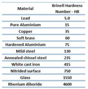
(https://www.nuclear-power.com/nuclear-engineering/materials-science/material-properties/hardness/brinell-hardness-number-brinell-scale/)
Attack:
#25 According to the NHRL rules, the robot spinner must come to a complete stop in 60 seconds or less.
#26
#27
#28 For weapon energy storage, we want to deal big damage. We approximated: Approx: m=4 lbs, spinner width 2″, length 8″, and omega of 240rpm or 3rot/s we get about 2J of energy using:
E = 1/2 I w^2 = (1/2) (1/12) (a^2 + b^2) * m * w^2
This is with a very small rpm. Since this scales with omega squared, this will be quite a high number. This joule value is reasonable to desire.
#29 The cost of the spinners must not exceed $500. Although steel is expensive, too expensive would not be worth it. We would be able to deal still a considerable amount of damage spinning something as simple as scrap of metal into a circular shape if we had to save money.
$30 We used the equation “Max Bite ~ Fwd Speed / (# Impactors * Weapon Speed)” to find our forward speed using a max bite of 1.5cm. This 1.5 cm is a rough estimate that is not just scratching the surface of a robot, and also is not huge chunks off for no force build up. Our team wants a medium ground of a good 1.5 cm. This value can be increased after prototyping for a slower spinner or faster mobility speed, but this rough estimate is the range we want to be in.
#31 The spinner must not weigh more than 6 pounds for weight reasons, and the spinner should be more than 2 pounds for impact efficiency reasons to deal sufficient damage.
System Grouping and Dependencies:
It is important to note that this system is a system. This system requires systems engineering, mechanical engineering, electrical engineering, and computer coding to all work together. Without understanding each subsystem individually and as a whole, this system would not come together correctly:
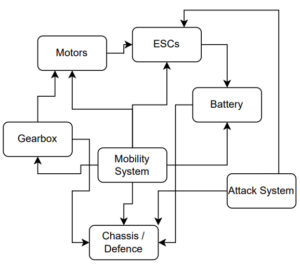
Many of these constrains affect another. One example is the motor constraints. When the motor becomes bigger in size and has a higher output power, there needs to be a scaled gearbox to accommodate for that change. Similarly, the motor also affects the ESC goals and constraints. When the motor needs more power, it needs an ESC that matches the amperage rating for that new motor. Similarly, a new battery might be necessary as well. Not only that, but then the chassis and gearbox might need to be changed for size or weight requirements as well. With over arching constraints such as size and weight, there is a balance beam of where does the weight and size go for various parts. Not only that, but also when one part changes, the specific variables for other parts change as well. If one part does not come in or is suddenly out of stock, the constraints and metrics help us choose a part that still will be viable and meet the requirements to make our robot work efficiently and well.