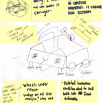

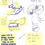
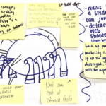
Our group members have watched numerous battle bots in motion in attempts to find commonalities in the most successful robot designs. Among these are lever arms that use momentum to damage the opposing robot and a chassis that is guarded by a ramp. We have also come up with our own potential weapons and safety systems. These could include pneumatics, retractable spikes, and maybe even a mesh exoskeleton. As we progress on this project, plan to devise new methods to compile the safest (and deadliest) designs into our best functioning robot.
We recognize that this combat robot will have a wide range of subsystems to navigate that include but are not limited to the attack system, the defense system, and the chassis. With different leaders heading each subsystem and a cohesive group work ethic, we believe that this challenging undertaking will prove rewarding. Each subsystem leader will head a group devoted to the design, prototyping, construction, and implementation of the subsystem while working with the robot’s system as a whole. Each group member will be expected to apply knowledge of CAD, MATLAB, mechanical, and electrical design to contribute to the growth of the overall project.
Though this project and design are in their preliminary stages, we have faith in our project’s ability to grow. Our team is a group with diverse mechanical engineering backgrounds, whose wide variety of design inputs will allow for a uniquely innovative final product.
This semester, our team want to build a battle bot that has both strong defense and attack with a high speed drive system. The solution space for weapon was to make a vertical spinner with extruded wedges at the front plate that could introduce the competitor into our attack range. For a strong construction, we choose thick aluminum plates to be our external frame. In order to have a good drive system, the idea was to use a powerful battery to supply three motors that could give enough torque to both wheels and spinner. Besides, since we expected that due to aluminum materials, the wheels need more torque to give enough drive force to move the bot forward, so, a transmission with two simple gears was used to ensure the output. Also, to take fully control of out bot, ESCs were necessary for the control and electrical system.
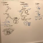
Potential Solutions:
- Mobility :
- Roller
- Hopper
- Weapon :
- Flipper
- Grabber
- Hammer
- Tethered projectile
- Spinner
- Vertical
- Horizontal
- Defense:
- Recovery tactics:
- Hydraulics to flip robot
- No designated up or down
- Mechanical arm
- Materials
- Recovery tactics:
- Control and Electrical system:
- ESC
- Gearbox
- Receiver
- Arduino
- Voltage
- Batteries
- Breadboard
- Safety:
- Kill switch- both on robot and remote
- Battery protection
- Additional method of movement
- Protected components (shield)
These robots require lots of creative design and NHRL specify looks for robots that are unique and creative. However these are strict rules that govern the combat robot design. These restrictions leave lots of room for creativity while keeping safety at the forefront. The robot should have the ability to move more than 4mph. Mobility of these robots is key. There are many methods of mobility of these robots that include wheeled, tracked, walking, crawling and even flying. These have a few limitations set in place about the methods of mobility allowing for creative solutions. A large aspect of this is ground clearance as this can prevent the robot from flipping. There is no limit on the ground clearance, however, the NHRL website states the floors may not be perfectly level.
A large safety aspect of the combat robot design is the implementation of a master switch. These switches must have the ability to completely deactivate the robot and be simple to use without putting the person at risk. The switch must also be accessible without changing the orientation of the robot. These kill switches must operate within the activation and deactivation time limit. These limits are that it cannot take more than 30 seconds to activate or deactivate the robot. The electrical limits of the robot are that it cannot exceed 220 volts without a nominal voltage above 60 volts. In addition, the batteries must be protected in order to prevent damage.
Controller specifications state that the robot must use commercially available remote controller that utilizes Digital Spread Spectrum. These also must be redundancies that if the transmitter loses connection from the robot the weapons are deactivated and the robot will stop moving. There is also a maximum setup time of 1 minute for RC communications. In addition, the robot must be compatible with a telemetry system provided by NHRL that’s approximately the size of an iphone.
The robot is limited in construction materials to exclude radioactive materials, hazardous fibers, toxic materials, organic materials and plastics, foam and rubber ceramics exterior components. In addition, the robots are allowed to use flames, hydraulics and internal combustion engines. However, due to our group experience we have decided to avoid using these components. The limitations of the use of pneumatics is that the robot must have its own air compressor and is limited to using nitrogen and compressed air. The pneumatic system must not exceed a sorted pressure of 3000psi and a regulated pressure of 400psi. The system must also include a method of purging the pneumatics as part of the deactivation process.
The safety of the operators and spectators is one of the main priorities of the combat robot community. In their rule book, they require that all sharp edges and blades of the robot must have removable covers that cannot be knocked off and must be mechanically fastened. In addition weapons that have the ability to move while deactivated must be properly secured.
Some Potential Designs of Weapons:
- Projectile Weapons: the projectile weapons cannot be explosive nor cause fouling problems. Springs, catapults, and gas-pressure-powered weapons will be feasible. Any projectile fired by a robot cannot exceed 370 ft/s.
- Multiple Weapons: a bot could be more competitive with many weapons, at least one of them should be capable of damaging or incapacitating the target. Using interchangeable weapons may be helpful. No matter how to set up those weapons, the bot cannot weigh more than the maximum weight.
- Spinning Weapons: spinning weapons must incorporate a fail-safe that removes power from the spinning parts, if the RC signal is lost. On instruction from the remote controller, spinning weapons must spin down from full speed to a complete stop within 60 seconds or if the RC signal is lost.
- Lifter / Flipper Weapons: The lifting or grappling weapon should be capable of lifting 30 lbs to a height of 12 in. A flipper bot should be able to launch a 30 lbs weight more than 2 fts into the air.
- Prohibited Weapons:
- Fouling devices such as glue, nets, fishing line, ball bearings and such.
- Squirting liquids or liquefied gasses such as liquid Nitrogen.
- EMP generators or other means intended to damage or jam the opponent bot’s electronics.
- Deliberate smoke generators.
- Bright lights, lasers, etc., that are distracting or dangerous to vision.
- Weapons that damage the other bot by destroying themselves.
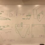
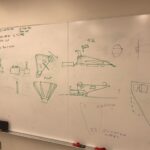
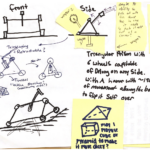
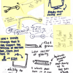
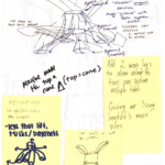
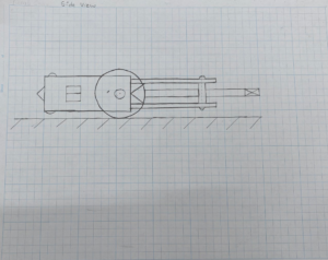
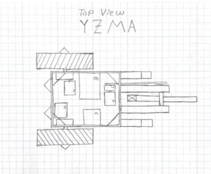
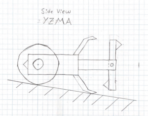
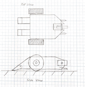
3 Potential Full Designs
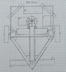
Final Solution and Specifications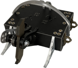
- Mobility:
- Motor: We chose a model 1100KV brushless motor outrunner motor for our wheels. This motor is 1100KV for fix-wing helicopter, and the max pull can up to 2150 grams. Shaft size is 5.0 x 65.5mm, recommend ESC for 40A and 12” prop to use.
- Wheels: The wheels and their belts were 3D printed.
- Weapon:
- Vertical spinner: After learning from previous years’ competition video, we found that most of bots were using vertical spinner. Our spinner has,
- Wedge: We made two wedge extruded at the front plate so that we could expect that with those wedges we could introduce competitor into our range of attack.
- Motor: We chose a model Prop Drive v2 4248 650KV brushless outrunner motor for our spinner. This motor has a maximum current 70A, maximum voltage of 19V and it is suitable for an ESC of 80A, a 4s~5s lipoly battery and a shaft with 5mm diameter. For the mounting, it has 4mm bullet and aims for 25 x 25mm bolt holes with a type of M3 bolt thread. With this motor, we can give our spinner a power of 1295W and a Kv ratio of 650 rpm/v.
- Defense:
- Materials:
- Internal: For all the internal, we use aluminum for both each size of shafts and the bearing. The axel rod was made of mulitpurpose aluminum with 1/8″ diameter and the plates were out of multipurpose 6061 Aluminum 1/8” Thick,12” x 24”
- Flip over method: We expected that our spinner could push against the ground to flip back the bot when the bot gets upside down.
- Materials:
- Control and Electrical system:
- Controller: We used FrSky Taranis Q X7 ACCESS 2.4GHz 24CH Radio Transmitter as our controller. The Taranis Q X7 ACCESS features 24 channels with a faster baud rate and lower latency due to its high-speed module digital interface. Just like the rest of the ACCESS transmitters, the Q X7 provides a secure and reliable link, along with wireless firmware, making it compatible with the newest line of OTA receivers. The battery compartment uses two 18650 Li-Ion batteries and can be balance charged via the Mini USB interface. This controller has ISRM-N internal RF module and the number of channels is 16 (ACCST D16) / 24 (ACCESS) channels.
- Arduino:
Solution Analysis
- Strength:
- Defense: Our external frame was strong enough to survive after several strikes from the competitor.
- Weapon: The vertical spinner works well and did some damage to opponent.
- Control: All motors worked well the control and the bot can move to the target place by giving the certain control. Both weapon and wheels can immediately stop if we would not give them any inputs.
- Weak:
- Mobility: Our bot did not move as we expected. It was not flexible enough and it was hard time for it to turn as fast as possible.
- Internal Shafts: The internal shafts were damaged, since the shafts were long and thin. We observed that the motor shaft to the spinner was broken after one fierce strike. We assumed that because the huge load of shear force was gathering on the shaft while shaft is brittle.
- Defense: Aluminum plates were strong. However, the deformation caused the internal layout of electricity was squeezed and the battery was broken.
- Connection: Left wheel motor connection was unplugged itself after match began. The wire connection was somehow not stable.
Sources:
[1] 2021 Design Rules – Battlebots.com. https://battlebots.com/wp-content/uploads/2021/06/BattleBots-Design-Rules-Rev.2021.0.pdf.
[2] “Types of Battlebots.” S.B.A. Invent, 11 July 2018, https://sbainvent.com/battlebot-design/types-of-battlebots/.
[3] Allain, Rhett. “The Physics of Terrifying Technological Battlebot Tactics.” Wired, Conde Nast, 27 Apr. 2018, https://www.wired.com/story/the-terrifying-technological-tactics-behind-battlebots/.
[4] Ann R. Thryft | Sep 22. “BattleBots & Their Designers Show off Moves & Design Tips.” Designnews.com, 9 Nov. 2016, https://www.designnews.com/automation-motion-control/battlebots-their-designers-show-moves-design-tips.
[4] Allain, Rhett. “The Physics of Terrifying Technological Battlebot Tactics.” Wired, Conde Nast, 27 Apr. 2018, https://www.wired.com/story/the-terrifying-technological-tactics-behind-battlebots/.