Subsystem: Attack System
Attack system was developed outside of the bot, and then inserted in. The danger associated with testing a weapon of destruction was enough to minimize testing of the actual weapon.
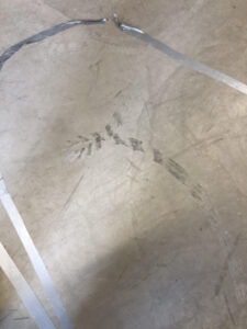
A model of the spinner was first attached to an old treadmill motor and moved into a piece of 2×4 wood. /this specific model of the spinner was a lot thinner than the final design, which resulted in tests where it ended up acting as a sawblade through wood. The final spinner was tested with the bot and ripped through a sheet of plywood.
The spinner model and test was great for the design validation of the spinner, however the attack system proved to only be as strong as its weakest component: the ½ in. aluminum shaft with a key slot. In combat, this shaft was sheared in two places, leading to the surrender of the bot.
Future design iterations would include developed system diagrams of all the components in the attack system, not just the weapon.
Subsystem: Maneuverability
Prototype: Maneuverability efforts were the most tested component of our combat bot. While the prototyping questions centered around: can we turn, go straight, and reverse? Can we accelerate to 10 mph in 2 sec? Can we stop in 1 foot? The testing questions quickly became: Does it work?
Tests included an assembled bot, with a driver and an open floor. Then tests developed into a maneuverability test where a duct tape line was drawn on the floor and the driver was challenged to stay on the line. Points were deducted for every waiver off of the line, and added to a raw time to complete the course.
The course included loops, zig zags, a straight section, multiple turns of various radii, and 3 point turns.
Quantitative results: Matt the driver scored a 58 after completing the course in 45 seconds and wavering 13 times. This was not impressive, but an emphasis on speed would have been more important if more practice was feasible.
Subsystem: Chassis Armor
Chassis arrangement was developed in an effort to fit everything in, be sturdy, and make components easy to access for maintenance. This began as a cardboard box to test to see if the dimensions were reasonable, which they were not. The next iteration became a 3d printed 1:2 scale model of the bot which served to ensure all the components of the chassis fit together. Finally this was manufactured out of water jet cut, ¼ in aluminum sheets.
Many prototyping questions arose: what impact can this withstand? Can this be punctured by a spinning mass? Will the armor stay mounted on the frame? Will the components fit inside easily?
Testing:
The only explicit test done on the chassis was a hardness test, which more or less confirmed published data about the hardness of aluminum.
Tests were conducted as a result of development of other systems, and the question of components fitting inside was answered as assembly began. However, the proposition of inserting an Arduino board, which was not necessarily required, was denied in part because of the difficulty in fitting it into the chassis. This should have been a place where iteration would facilitate the manufacturing of a larger chassis.
Additional tests were done while testing the maneuverability where we set out with the goal of seeing where weak points in our fasteners were by accelerating, turning, and stopping until some nut, bolt, or set screw came loose.
At this point, the chassis fits everything we need, but would need to be made larger. After the testing that came as a result of entering the NHRL competition, it was clear the aluminum sheets were not strong enough to be used, external components were not mounted well enough, and external components were too slim to be effective.
Subsystem: Electronic Communication
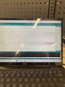
After doing extensive research, some electronic speed controllers (ESCs), motors, and a transmitter and receiver were ordered and development of the electronics system communication began. This happened around the same time the chassis began manufacturing. Fabrication of the electronics system involved acquiring some wires, an Arduino Uno board, and a breadboard. Then communication testing with the transmitter and receiver began. This was based off of our prototyping plan for communications, where we asked “Does our transmitter and receiver work while enclosed in metal?” We passed this test with a success scale of 3/3 which indicated both the attack and mobility systems worked together.
Subsystem: Electronic Control
Using the ESCs connected to the receiver was a preliminary prototype that resulted in being the final electrical system. Throughout the semester prototypes of more advanced control were developed with the use of the Arduino board. This began simplistically by being able to read transmitter values outputted from the receiver.
Then it became necessary to interpret and replicate those signals to output to the ESCs from the Arduino. This became an issue of whether or not the signal could be consistently and accurately interpreted by the Arduino. The Arduino system allowed us to use one input signal to control two ESCs, which was desirable for forward and back movement, and also allowed us to scale the inputs from the receiver to be more realistic and on a better scale than the default capabilities of the ESC-receive
r direct connection system.
Updated Prototyping Plan
Subsystem: Mobility & Attack
The objective of this report is to clearly describe the process of determining the success of the mobility and attack subsystem and providing a pathway for reiteration of our designs.
Outline
- Mobility
- Can our mobility subsystem move forwards, backwards, and turn? -> Yes
- Can our mobility system accelerate to 10 ft/s within 3 seconds? -> Yes
- Can our mobility system completely stop from full speed within a foot? -> Yes
- Attack
- Can our robot power down within a reasonable amount of time? -> Yes
- Can our attack system function while the combat bot is in motion? -> Yes
- How strong is our vertical spinner? -> Unanswered
- Communications
- Does the receiver work when enclosed in metal? -> Yes
Mobility
Frame
Critical question: Can our mobility subsystem move forwards, backwards, and turn? -> Yes
Prototyping Lens: Viability
Context: We want to figure out whether or not our mobility subsystem would be able to maneuver efficiently in a battle from remote control.
Prototyping Purpose: Evaluate
Minimum Requirements: Be able to control the combat bot’s movements forward, backwards, and turn in place by remote control for at least 32 feet or 5 seconds in each direction.
Build
Prototype Type: Works- Like
Fidelity: Low
Media & Fabrication: Physical Components
Resources & Limitations: Need an empty area for testing, tape measurer, and tape to use as markers.
Build Sketch:
Test
Prototype Test:
- Find an open space
- Set a combat bot on the ground with or without a spinner attached.
- Use remote control to attempt to move
- Visually measure success of movement
Success Criteria:
- Success will be rated on a scale of 1-5 with 5 being the most successful.
- 1 if no movement is achievable, or if target finish is not reached in any direction.
- 2 if movement is achievable in 1 direction.
- 3 if movement is achievable in 2 directions.
- 4 if movement is achievable in 3 directions.
- 5 if movement is achievable in 4 directions.
Data Collection: Visual.
Act
New Insights & Ideas: Adapt to encompass all tests in one
Actions: Convert to line following test
Documentation & Sharing:
Mobility
Frame
Critical question: Can our mobility system accelerate to 10 mph within 2 seconds? -> Unanswered
Prototyping Lens: Desirability
Context: In order for our combat bot to be successful in the arena, it must be able to get to the center of a 16 foot arena within 2 seconds.
Prototyping Purpose: Evaluate
Minimum Requirements: Be able to move forward 16 feet within 2 seconds.
Build
Prototype Type: Works- Like
Fidelity: Low
Media & Fabrication: Physical Components
Resources & Limitations: 16 feet of clear space, tape measurer, and a timer.
Build Sketch:
Test
Prototype Test:
- Find open space.
- Set Battlebot on ground with a spinner attached but not active.
- Attempt to move robot forward 16 feet to the finish line.
- Time how long it takes to complete the sprint.
- Calculate mph.
Success Criteria:
- Success will be rated on a scale from 1-5 with 5 being the most successful.
- 1 if no movement is achieved, or if the finish line is not crossed within a reasonable amount of time.
- 2 if the finish line is crossed after 4 seconds have passed.
- 3 if the finish line is crossed sometime between 2-4 seconds.
- 4 if the finish line is crossed in 2 seconds.
- 5 if the finish is crossed below 2 seconds.
Data Collection: Visual/ Video.
Act
New Insights & Ideas: For competition in April, the question of does it move was more important than how fast can it accelerate.
Actions:
Documentation & Sharing:
Mobility
Frame
Critical question: Can our mobility system completely stop from full speed within a foot?
Prototyping Lens: Desirability
Context: In order to be successful in combat, our battle bot needs to be able to make quick stops and turns to both escape and attack opponents.
Prototyping Purpose: Explore
Minimum Requirements: Be able to bring the battle bot to a complete stop from full speed within a half foot.
Build
Prototype Type: Works- Like
Fidelity: Low
Media & Fabrication: Physical Components
Resources & Limitations: Need approximately 32 feet of clear space, tape, and tape measurer.
Build Sketch:
Test
Prototype Test:
- Find an open space
- Place the battle bot on the ground with a spinner attached but not turned on.
- Accelerate battle bot to full speed
- Brake at breaking point
- Gauge how far combat bot takes to come to a complete stop
Success Criteria:
- Success will be rated on a scale from 1-5 with 5 being the most successful.
- 1 if combat bot does not brake at all or if it stops after 1 foot
- 2 if combat bot stops 1 foot from breaking point
- 3 if combat bot stops within 6”-1’ from breaking point
- 4 if combat bot stops at 6” from braking point
- 5 if combat bot stops somewhere in between 0”-6” from breaking point
Data Collection: Visual
Act
New Insights & Ideas: For competition in April, the question of does it move was more important than how fast can it accelerate.
Actions:
Documentation & Sharing:
Attack
Frame
Critical question: Can our attack system turn off within a reasonable amount of time? -> Yes
Prototyping Lens: Viability
Context: In order for our combat bot to only attack other robots and not humans, we need it to power down within a reasonable amount of time
Prototyping Purpose: Evaluate
Minimum Requirements: Vertical spinner powers down to a complete stop within a minute.
Build
Prototype Type: Works- Like
Fidelity: Low
Media & Fabrication: Physical components
Resources & Limitations: Need a clear, protected space to observe battle bot and a timer.
Build Sketch:
Test
Prototype Test:
- Create a clear space with a protected viewing area
- Place battle bot with spinner attached in testing area
- Turn on the vertical spinner and let it run for approximately 10 seconds.
- Hit the kill switch.
- Time how long it takes for the vertical spinner to come to a complete stop.
Success Criteria:
- Success will be rated on a scale from 1-5 with 5 being the most successful.
- 1 if vertical spinner does not come to a complete stop within 60 seconds
- 2 if vertical spinner comes to a complete stop at 60 seconds
- 3 if vertical spinner comes to a complete stop at 40 seconds
- 4 if vertical spinner comes to a complete stop at 20 seconds
- 5 if vertical spinner comes to a complete stop after a few seconds or almost instantly
Data Collection: Visual
Act
New Insights & Ideas: Required for safety test at NHRL
Actions:
Documentation & Sharing: Passed safety check
Attack
Frame
Critical question: Can our attack system function while the combat bot is in motion? -> Yes
Prototyping Lens: Viability
Context: In order for our combat bot to actively attack the opponent, it needs to be able to use its weapon while moving.
Prototyping Purpose: Evaluate
Minimum Requirements: Vertical spinner is active while mobility system is in use.
Build
Prototype Type: Works- Like
Fidelity: Low
Media & Fabrication: Physical components
Resources & Limitations: Need a clear, protected space to observe battle bot
Build Sketch:
Test
Prototype Test:
- Create a clear space with a protected viewing area
- Place battle bot with spinner attached in testing area
- Attempt to move combat bot and turn on spinner at the same time.
Success Criteria:
- Success will be rated on a scale from 1-5 with 5 being the most successful.
- 1 if the spinner and mobility subsystem can be used, but not at the same time.
- 2 if the spinner and mobility subsystem can be used while the battle bot moves in one direction.
- 3 if the spinner and mobility subsystem can be used while the battle bot moves in two directions.
- 4 if spinner and mobility can be used while the battlebot moves in all directions.
- 5 if the spinner and mobility subsystem can be used simultaneously with no restrictions.
Data Collection: Tested implicitly while testing spinner capabilities
Act
New Insights & Ideas: Start up and stopping the spinner during maneuvering should have been tested
Actions:
Documentation & Sharing:
Attack
Frame
Critical question: How strong is our vertical spinner?
Prototyping Lens: Desirability
Context: In order for the combat bot to win a battle, it needs to be able to cut through any material that is presented to it.
Prototyping Purpose: Explore
Minimum Requirements: Combat bot can cut through all metal that is less than its own HB value.
Build
Prototype Type: Looks- Like
Fidelity: High
Media & Fabrication: Will need space for testing, but also materials of different hardnesses to try to cut through. (Different types of steel)
Resources & Limitations: Need a clear, protected space to observe battle bots, but also 1” sheets of metal to try to cut through. Metal sheets will be made out of hardened aluminum (HB=95), mild steel (HB=130), and annealed chisel steel (HB=235).
Build Sketch:
Test
Prototype Test:
- Place combat bot in a protected space
- Turn on mobility system and attack system
- Have combat bot attack 1” metal sheet
Success Criteria:
- Success will be rated on a scale from 1-6 with 6 being the most successful.
- 1 if combat bot cuts partially through hardened aluminum
- 2 if combat bot cuts through hardened aluminum
- 3 if combat bot cuts partially through mild steel
- 4 if combat bot cuts through mild steel
- 5 if combat bot cuts partially through chisel steel
Data Collection: Visual
Act
New Insights & Ideas: Spinner strength is irrelevant: an attack system is only as strong as its weakest component
Actions: Test entirety of system. Model every component
Documentation & Sharing: Spinner shaft shearing
Communications
Frame
Critical question: Does our transmitter and receiver work while enclosed in metal? -> yes
Prototyping Lens: Viability
Context: In order for the combat bot to win a battle, it needs to be able to operate by remote control. To obtain communications during the entire battle, the receiver must be inside the battle bot as to avoid being potentially disabled by an opponent.
Prototyping Purpose: Evaluate
Minimum Requirements: RC works even when the transmitter is encased inside the battle bot.
Build
Prototype Type: Works- Like
Fidelity: Low
Media & Fabrication: Will need space for testing.
Resources & Limitations: Need a clear, protected space to observe battle bot
Build Sketch:N/A
Test
Prototype Test:
- Place combat bot in a protected space
- Turn on mobility system and attack system
Success Criteria:
- Success will be rated on a scale from 1-3 with 6 being the most successful.
- 1 if combat bot does not work by RC
- 2 if combat bot’s mobility system works by RC
- 3 if combat bot’s attack system works by RC
- 4 if combat bot’s attack and mobility system works by RC cuts
Data Collection: Visual
Act
New Insights & Ideas:
Actions:
Documentation & Sharing:
Updated Schedule
| DATE | EVENT |
| Mar 28, 2022- Apr 1, 2022 | Complete First Prototype/ Redesign and Retest |
| Apr 4, 2022- Apr 8, 2022 | Prototype Mobility and Attack/ Redesign and Retest |
| Apr 11, 2022 | 5 Minute Update |
| Apr 12, 2022- Apr 15, 2022 | Final Prototype Finished |
| Apr 18, 2022- Apr 22, 2022 | Learning how to operate functional robot/ Community Outreach |
| Apr 23, 2022 | Competition Day |
| Apr 25, 2022- Apr 29, 2022 | Assess Outcomes |
| May 2, 2022- May 6, 2022 | Potential Repair and Final Presentation Prep |
| May 9, 2022- May 10, 2022 | Potential Repair and Final Presentation Prep |
| May 11, 2022 | Final Prototype Demonstration and Poster Presentation |
| May 12, 2022 | Final Website Update |
Updated Budget
| Expense | Subsystem | Description | Date Ordered | Vendor | Budget | Actual | Difference ($) | Notes | |
| All Motors | $ 111.00 | $ 148.95 | $ (37.95) | ||||||
| Attack Motor | Attack | PROPDRIVE v2 4248 650KV Brushless Outrunner
Motor |
12/1/2021 | HobbyKing | $ 37.00 | $ 73.98 | $ (36.98) | Two motors were purchased so that we could always have a backup on hand | |
| Battery | RC | Turnigy 4000mAh 5S 30C Lipo Pack w/XT-60 | 12/1/2021 | HobbyKing | $ 75.00 | $ 42.98 | $ 32.02 | Bought on sale – will be purchasing a backup soon | |
| Transmitter/Receiver | RC | RadioLink AT9S PRO 2.4GHz 12Ch Transmitter w/ Receiver | 1/30/2022 | Robot Shop | $ 178.00 | $ 129.99 | $ 48.01 | Budgeted separately, bought together | |
| Battery Charger | RC | EBL 1S-6S LiPo
Battery Charger |
2/10/2022 | Amazon | $ – | $ 47.99 | $ (47.99) | Not Accounted for, could be included in Battery budget | |
| Mobility Motors | Mobility | 3 X 1100KV Brushless Motor Outrunner | 2/10/2022 | Amazon | $ – | $ 74.97 | $ (74.97) | Not Accounted For | |
| Voltage Checker | RC | Apex RC Voltage Checker | 2/10/2022 | Amazon | $ – | $ 9.99 | $ (9.99) | Nol Accounted For | |
| Wires | RC | 3 X 6Pack 7.87″ 14AWG 4.0mm Bullet
Connector |
2/10/2022 | Amazon | $ – | $ 26.97 | $ (26.97) | Not Accounted For, could be included in wires budget | |
| ESC Connector | RC | 2 X XT60 quad
connecter for battery to ESCs |
2/10/2022 | Amazon | $ – | $ 14.98 | $ (14.98) | Not accounted for, could be included in ESC budget | |
| All ESCs | RC | $ 90.00 | $ 184.36 | $ (94.36) | |||||
| ESC | RC | DYS Aria 70A Blheli_32 ESC | 2/17/2022 | Robot Matter | $ 38.98 | Was this received? | |||
| All Defense Armor | Chassis | $ 200.00 | $ 407.03 | $ (207.03) | We have enough to manufacture 2 bots | ||||
| Aluminum Armor | Chassis | Multipurpose 6061 Aluminum Sheet 1/8″
Thick, 12″ x 48 |
2/17/2022 | McMaster | $ 100.05 | ||||
| Aluminum Armor | Chassis | Multipurpose 6061 Aluminum, 1/4″ Thick,
12″ x 48″ |
2/17/2022 | McMaster | $ 109.41 | ||||
| Aluminum Armor | Chassis | Multipurpose 6061 Aluminum, 1/2″ Thick,
12″ x 48″ |
2/17/2022 | McMaster | $ 197.57 | ||||
| Voltage Regulator | RC | 4Pack DC-DC
Buck Converter, Adjustable Step Down Voltage Regulator 3-40V to 1.5-35V |
2/17/2022 | Amazon | $ 10.00 | $ 9.39 | $ 0.61 | These are the savings we need. | |
| ESC beast | RC | 3 X
1HobbyKing® ™ X-Car Beast Series ESC 1:8 Scale 120A |
2/21/2022 | HobbyKing | $ 145.38 | ||||
| Connector | RC | OliRC 2pcs
XT60 Connector Plug to 4mm Banana Plugs Battery Charge Lead Adapter Cable 12awg 30cm |
3/3/2022 | Amazon | $ 30.00 | $ 10.99 | $ 19.01 | ||
| Socket Head Screws | Chassis | Low Profile socket 3/4 | 3/3/2022 | McMaster | $ 10.19 | ||||
| Washers | Chassis | oversized washers | 3/3/2022 | McMaster | $ 8.52 | $ (8.52) | |||
| Bolts | Chassis | 2 X Bolt 3/4 10-24 | 3/3/2022 | McMaster | $ 38.76 | $ (38.76) | |||
| Socket Head Screws | Chassis | low profile socket 1in | 3/3/2022 | McMaster | $ 13.48 | $ (13.48) | |||
| Bots | Chassis | bolt 10-24 1in | 3/3/2022 | McMaster | $ 19.38 | $ (19.38) | |||
| Pully | Attack | 1.5in timing pully | 3/3/2022 | McMaster | $ 21.64 | $ (21.64) | |||
| Pully Wheel | Attack | timing pully 1.13in | 3/3/2022 | McMaster | $ 9.25 | ||||
| Washers | Chassis | standard washers | 3/3/2022 | McMaster | $ 5.11 | ||||
| Bearings | Attack | 3 X 1/2 bearing | 3/3/2022 | McMaster | $ 19.95 | ||||
| Bearings | Mobility | 6 X 1/4 bearing | 3/3/2022 | McMaster | $ 41.22 | ||||
| Nut | Chassis | 10-24 narrow nut | 3/3/2022 | McMaster | $ 9.32 | ||||
| Nut | Chassis | 10-24 Nut | 3/3/2022 | McMaster | $ 5.35 | ||||
| Bearings | Mobility | 2 X 5mm bearing | 3/3/2022 | McMaster | $ 39.00 | ||||
| Gear | Mobility | 2 X 12 tooth gear | 3/3/2022 | McMaster | $ 35.18 | ||||
| Gear | Mobility | 2 X 48 tooth | 3/3/2022 | McMaster | $ 84.36 | ||||
| Timing Belt | Operating | Timing Belt | 3/11/2022 | $ 7.95 | $ (7.95) | ||||
| Axel Rod | Mobility | Multipurpose aluminum 1/8″ diameter | 3/11/2022 | $ 2.05 | $ (2.05) | ||||
| Timing belt | Attack | Timing Belt | 3/11/2022 | $ 8.15 | $ (8.15) | ||||
| Timing belt | Attack | Timing Belt | 3/11/2022 | $ 7.73 | $ (7.73) | ||||
| Wheel O-rings | Mobility | 1/8″ O-ring | 3/11/2022 | $ 200.00 | $ 14.91 | $ 185.09 | |||
| Totals: | $ 931.00 | $ 2,175.46 | $ (1,244.46) | Oof |