1.Thermal, Mechanical, and Hybrid Chemical Energy Storage Systems
Source: K. Brun, T. AllisonとR. Dennis, Thermal, Mechanical, and Hybrid Chemical Energy Storage Systems. London San Diego, CA Cambridge, MA Kidlington, Oxford: Academic Press, an imprint of Elsevier, 2021. [1]
We used the first chapter of this textbook source to obtain an introductory understanding of energy storage.
Energy storage systems are designed to store energy when excess renewable power is available and release the storage energy to meet demand when renewable power drops. The end goal is to displace traditional fossil and nuclear fueled power plants. Motivation to achieve this goal is presented among OECD (Organisation for Economic Co-operation and Development) countries, as statistics show that usage of renewable sources for electricity production is increasing yearly.
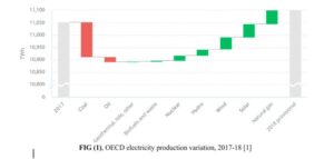
Figure (1) below shows a waterfall chart of the electricity production among OECD countries between 2017 and 2018. Red bars represent decline in usage of fossil fuels (coal and oil) and green bars represent growth in renewables(solar and wind have the largest growth).
There are also other justifications in stating that Renenwables will continue to expand. Paris Agreement (2016), signed by 186 states of the EU which represent 97% of global greenhouse emissions, states that their goal is to lower greenhouse gases and increase renewable energy production so that global warming is mitigated.
However it is important to note that two challenges result from rapid introduction of renewables into Energy Mix. Firstly, solar and wind generators have high variability. Solar input is only available when the sun is shining, which peaks midday, and wind varies throughout the day and year. Secondly, the availability of renewable resources is poorly matched to the daily power demand profile. This profile is presented through the duck curve shown in figure (2).
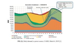
The red dashed line represents the daily demand for electricity. The curve shows that the demand peaks in the morning and the evening. During evening peak, solar production drops off, so energy sources must be brought on quickly. These imposed ramp ups and turndowns are not compatible with efficient generators. Generators with the fastest rates (simple-cycle gas turbines) have poor efficiency and emission performance. During the middle of the day renewable product (plus baseload) exceeds demand, requiring curtailment (shut off) of renewables to balance power. Energy curtailment has been required every month since December 2016.
Opportunities and challenges for energy storage were also discussed. Some constraints include: function reliably, efficiently, and cost effectively at grid scale. The necessary quantity of storage required in the long term is dependent on a few factors: depth of renewable penetration in energy mix, relative size of solar/wind generation, grid size/diversity, geography and climate, degree of allowable energy curtailment, storage system performance capabilities , and economic Policy. Many authors conclude that storage requirements should approximately equal the daily average energy demand. If energy storage gets too big (scale-wise) serious issues of location and safety are raised.
2.Compressed Air Energy Storage, Red Mountain Insights
Source: L. Red Mountain Insights, Utility energy storage: profiles batteries, compressed air storage, flywheels, hydrogen, superconducting magnetic energy storage, thermal energy storage, ultracapacitors, and vehicle-to-grid. 2012. [Online]. Available at: http://public.ebookcentral.proquest.com/choice/publicfullrecord.aspx?p=3400007 [2]
This section of the source discusses the concepts and functions behind a compressed air energy storage system.
Compressed air storage system (CAES) uses excess renewable power to compress air into a storage tank (Large scale: salt cavern, abandoned hard rock mine. Small scale: pressurized tanks) that is then released during peak hours into a power transducer such as a turbine/generator for energy production. This technology is used to substitute the more expensive gas turbine-produced power, which compresses air and uses combustion as the power source. It has the ability to produce two to three times as much power as conventional gas turbines for the same amount of fuel.
There are three different types of CAES: adiabatic storage, diabatic storage: isothermal compression and expansion approaches. An adiabatic storage reuses the heat produced during the air compression, and returns it to the air when it is expanded through the turbine to generate power. Theoretically it is the most efficient system because there would be no heat loss. A diabatic storage reaches isothermal compression by releasing heat into the atmosphere using intercoolers (heat loss). The air will then be reheated, using a natural gas burner or a heated metal mass, prior to expansion in the turbine to power a generator. This contributes to heat loss within the system but it is the simplest approach and for that reason it has been used the most commercially. Isothermal Compression and Expansion Approaches attempts to maintain operating temperature by constant heat exchange to the environment but it is only practical for low power levels. Theoretically 100% efficient but in practice this is unobtainable due to unavoidable heat losses. For all three types, “compression can be performed using electrically powered turbo-compressors and expansion with turbo ‘expanders or air engines to produce electricity. Small scale compressed air energy storage includes air cars and air-driven locomotives.
There are a couple systems that can be implemented in a CAES: hybrid systems, lake or ocean storage. A hybrid system generally uses the Brayton cycle engine. Notable hybrid CAES power plants include Huntorf, Germany and Mcintosh Alabama. Lake or ocean storage uses hydrostatic pressure on the vessel. This takes away the necessity of using a high-pressure vessel or drilling into salt caverns and aquifers.
The performance of a CAES can be compared to batteries. In terms of energy density, new batteries are better than CAES. Batteries can provide electricity at a constant voltage at any percentage of its capacity but for a CAES the pressure level varies. Due to its varying pressure, it is difficult to design a CAES system that can operate at high efficiency at a wide range of pressures. However CAES systems excel in longevity compared to conventional batteries which also has issues related to material waste.
3.Different Energy Storage System Technologies for Microgrid Applications and Issues/Challenges
Source: M. Faisal, M. Hannan, P. J. Ker, A. Hussain, M. B. Mansor, and F. Blaabjerg, “Review of Energy Storage System Technologies in microgrid applications: Issues and challenges,” IEEE Xplore, 12-Jul-2018. [Online]. Available: https://ieeexplore.ieee.org/document/8368103. Available at: https://ieeexplore.ieee.org/document/8368103 [Accessed: 03-Oct-2021]. [3]
This section of the source goes into detail about the different types of energy storage system technologies that there are currently. Also, it discusses the application of using an energy storage system in conjunction with a power system. Figure 3 does a great job of giving a comprehensive and general overview of this application.
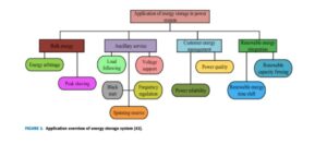
The various implementations that we could use with energy storage are immense, which can be seen in Figure 3, further proving just how important and beneficial creating successful and useful energy storage systems would be in regards to our grid.
Energy storage systems can be either chemical, electrochemical, electrical, thermal, hybrid, or mechanical. The one we will be focusing on is the mechanical type of energy storage system. There are three main types of mechanical energy storage: flywheel, pumped hydro, and compressed air. There are also Gravity Energy Storage systems (GES).
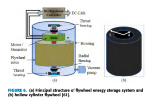
A flywheel is a magnetically levitated disk that is supported by a stator. Flywheels are beneficial because they can be used for mechanically storing kinetic energy by using a rotor mass that is spinning at high enough speeds. The flywheel efficiencies are pretty high, ranging from 90%-95%. Their power outputs range from 0 MW to 50 MW. The initial investment for this technology is high, costing $5000 per KWh, but the maintenance costs are low, at $19 per KW-year. The big advantage with flywheel energy storage is that there does not have to be temperature regulation. Figure 6 shows the structure of the storage system.
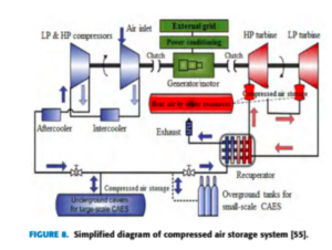
The next mechanical energy storage system is the Compressed Air Energy Storage system (CAES). In this process, gas is compressed and stored in a reservoir. A turbine is then used to expand the gas to convert it to mechanical energy. When the energy is not needed, the surplus power is driven by a reversible motor that then uses compressors to put the gas back into wherever it is being stored. When it is needed, the gas is released from the storage area and heated up by some heating element where it eventually makes its way to the turbine. This system can be scaled to any size, although it works better for a large scale system. There are a few CAES plants in practice, such as one in Germany and Alabama. The process of how the CAES operates is seen in Figure 8.
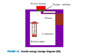
The last form of mechanical energy, outside of pumped hydro, is Gravity Energy Storage systems (GES). GES is a pretty new concept so it is still a technology in progress. It uses a generator, reversible turbine, piston, and container that has a return pipe. When energy is needed, the piston is initiated and pushes the water to the container to be passed through the return pipe. This helps to propel the turbine which converts kinetic energy into mechanical energy to spin the generator, which in turn produces electricity. This process is reversed when energy demand is low. The schematic diagram for this system can be seen in Figure 10.
4.Interview with Scott Baker
Scott Baker is a Business Solution Engineer at PJM Interconnection; a regional transmission organization (RTO) that coordinates the wholesale and pricing movements of electricity within the region of 13 states. Manages the largest power grids in North American. His job is to monitor the reliability and real time operation systems of bulk power systems. In regards to his expertise in the supply side of energy production, we decided to ask him a few questions that may help us with understanding our problem statement.
What we discussed:
Electrical vehicle power demand predictions/implementation. Scott Baker predicts that EV will still be considered a small factor to the transmission system 15 years from now. The impacts of EV are more likely to be felt at small scale grids such as individual homes. PJM also doesn’t expect to implement real time communication for EV charging unless consumers aggregate EVs into the wholesale market (10000 MW of distributed energy resources).
Distributed energy resources (DER), is a huge area of growth in the present and the near future. However many challenges are associated with DER at the aggregator level, such as methods to enable communication with DER make them cost effective. It becomes complicated when small scale resources are bidded into a market that was made for large scale power plants. Policies are being made to overcome these challenges. Order 2222 enables DER aggregators to compete in all regional organized wholesale electricity markets. This enforces RTOs to make way for DER regulators to participate in markets.
Transmission Network Reliability is one of the main focuses of PJM. Monitoring reliability ties into following national standards of North American Electric Reliability Corporation (NAERC). These standards include plants maintaining certain voltage levels, certain frequency tolerance and keeping enough reserves on the system (prevention of major blackouts). Violation of these standards causes PJM to get heavily fined. Texas blackouts led to every single commissioner getting fired from not being able to comply with the standards.
The incentive for district size CAES is unperceived at the moment. There is a market but most people are leaning towards the usage of batteries. PJM and smaller utilities are using batteries to peak shave the grid. Aging infrastructure can be addressed with energy storage, but buying new substations takes time so batteries are being used as an alternative. Also depending on the type of system, CAES has problems with roundtrip efficiencies (diabatic storage).
Local/Residential Energy storage (nanogrids) are increasing in popularity. As an example, local solar installations are going up in Texas after the blackout disaster. Scott believes that these nano scale grids are extremely reliable. He mentioned that high performance electric cars that can support energy storage are in development (Ford F150).
5.Experimental performance study of a hybrid compressed
air-electric vehicle prototype
- A. Evrin&I. Dincer, 「Experimental performance study of a hybrid compressed air‐electric vehicle prototype」, Energy Storage, vol. 2, no. 6, December 2020, doi: 10.1002/est2.195.
This paper discusses the development of a hybrid compressed air-electric vehicle. It doesn’t exactly tie into energy storage, but it gives us a physical presentation of a CA system that directly provides output power.
The author proposes the usage of a phase change material (PCM) to act as an absorber to avoid heat losses. Out of the three PCMs investigated, paraffin shows the best results. The hybrid prototype was built and tested at a laboratory at Ontario Tech, and results show sufficient power output for a small size city vehicle. The energy efficiency of this vehicle exceeds the efficiency of a common commercial pneumatic vehicle.
Literature Review Continued
https://patentimages.storage.googleapis.com/e1/18/20/6cffdb751856d0/WO2011076926A2.pdf
This patent was filed on December 23rd, 2010 by Global Power and Energy Ltd. The patent and corresponding diagrams outline a large-scale adiabatic compressed air energy storage system used to supplement energy on an electrical grid. The author blueprints a system that uses extra energy from the grid or from renewable sources to compress air into a cavern for later use. To improve the efficiency of the system, heat from the compression process is stored and applied to the air upon decompression to increase the energy output of the system.
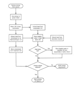
The above is the flow diagram for the storage phase of the compressed air energy storage process. This logic would be used for compressing air when surplus energy from the grid or from renewable sources is detected.
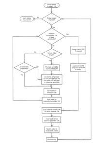
The above is the flow diagram for the energy generation phase of the compressed air energy storage system. This logic would be used for decompressing air and directing it through a modified turbine when energy output is required for the electrical grid.
https://patentimages.storage.googleapis.com/ef/55/b1/d441b7a479eb09/US3831373.pdf
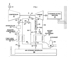
This patent outlines a pumped air storage peaking power system that is composed of a single shaft gas turbine-generator unit used in conjunction with a system of valves. This developed system uses three modes: pumping mode where extra energy is used to compress air that is then stored in the gas chamber; peaking mode where previously stored compressed air is released through a turbine to generate energy; and a final mode where the system acts as a conventional gas turbine operating with ambient air. These modes are all operated and controlled by the valves onboard the system.
