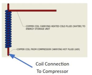
The purchase of the compressor this semester allowed the heat exchanger team to finalize decisions for the heat exchanger. Using our design matrix (see below) we determined that the coil water to air design would be best. The brazed plate design, while ranked the highest, was ultimately deemed too expensive for the project. The exposed copper coil on the compressor allows us to easily attach copper tubing for use as part of our heat exchanger. This heat exchanger will use water as the cooling fluid and the hot air from the compressor as the heating fluid. The copper coil we’ve selected will be a half-inch, the same diameter as the copper tubing of the compressor. We will coil the copper tubing as tightly as possible around the compressor tubing to maximize heat transfer. We will also use thermal paste or soldered connections with this tubing to increase the heat transfer possible between the air and water. As the water is heated, it will move through insulated tubing to the thermal energy storage vessel where water will heat more copper tubes in the discharge process. Preliminary calculations were done modeling the heat exchanger as a counter-flow shell and tube heat exchanger.
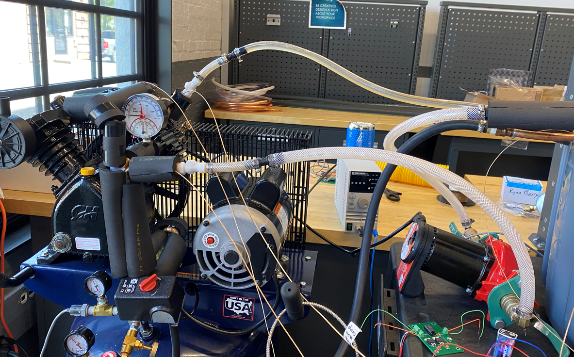
The heat exchanger is one of the most design-heavy subsystems of our project since its components came from scratch and eventually came together. Hence, we went through numerous iterations of piping material selection, disconnect adjustment, leak-proofing, etc. For one, we started off with vinyl tubing and quickly came to realize that it has kinking problems near junction points. This was a pretty serious issue since kinking could drastically reduce or even stop the flow of water from circulating through the heat exchanger system – thereby rendering super low HX effectiveness and throwing off the cost-benefit trade-off of having a heat exchanger system in the first place. One of the requirements for the HX proto-typig requires us to implement parts that would allow us to gather flow rate which we planned to do using an ultrasonic flow meter. However, an unexpected change that was created was a change to a portion of piping from reinforced vinyl to PVC since we realized that the ultrasonic waves require rigid piping to properly deflect. Leak-proof is an important standard to meet for any HVAC system. Initially, we had thought of using hose-clamps and teflon tape and later realized that for metal-metal connection, solder-seal through capillary heating was very much necessary to ensure that there would be no metal leaks. This also has the added benefit of reducing the chances of impurities or rusting or external elements – thereby prolonging the life of our system. Lastly, although outlet base temperature was met, our HX effectiveness is only ~ 30% which makes the cost-benefit ratio unfavorable since more energy was used by the pump to conduct the work than what was reaped. In other words, it is marginally more energy efficient to directly heat the piping exterior which led us to look into renewable energy source feed in order to rationalize the need for the heat exchanger from a cost-benefit perspective. However, since the project was on a tight timeline and budget, we could not exactly install solar panels/wind turbines/hydro pumps to test out as of yet.
Specification Notes
- Heat Exchanger- Pressure Drop
- Pressure Drop for the heat exchanger subsystem is the pressure loss occurring through the system of copper tubing moving from the charging process to the discharge. This specification is important because it helps identify an appropriate pump to move water through the tubing. The pressure drop was calculated using bernoulli’s equation, operating under the assumptions: (1) the elevation was negligible, (2) flow is incompressible, (3) and steady flow. Minor head losses were calculated using a piping design that includes four 90 degree bends. Major head losses were calculated using the Reynolds number and corresponding Moody chart. The pump curve given by the manufacturer showed the flow rates that would be achievable based on the pressure drop calculated. The highest flow rate fell just under the pump curve, making the associated pressure drop the upper bound. Similarly, the lowest bound was calculated through the lowest flow rate and pump curve. Our target value falls around the middle of the pump curves from the manufacturer.
- Heat Exchanger – Thermal Energy Storage Vessel Size
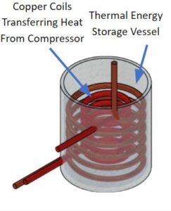
- The thermal energy storage vessel for this heat exchanger stores the heat of compression in stationary water, and then this heat is used to charge the air motor during discharging. This specification is important because the storage vessel is a key component of heat exchanger systems and the vessel needs to house tubing for the discharging and charging states. It’s dimensions need to house the maximum radius of the coiled copper tubing, but also needs to be sturdy enough to hold at least 10 gallons of water without failing. For prototyping, the heat exchanger will not need insulation as an ideal charging and discharging cycle will be completed without pause. Having a plastic storage vessel ensures there is as little heat loss to the environment as possible.
- Heat Exchanger – Maximum Outlet Temperature
- The heat of compression is stored in the thermal energy storage vessel and then discharged through tubing to the air motor. The maximum outlet temperature during the discharging stage would ideally be as close to the heat of compression as possible. This is not feasible, however, due to heat loss to surroundings through the storage vessel or tubing, but precautions using shorter pipe length and insulation can help keep this temperature as high as possible.
- Pipe Length
- Considering that the energy storage container has a height of about 3 ft, this means that the total coil height of the piping must be below that. Hence, about 50 – 90 ft of piping should suffice while remaining within geometric constraints. The lower bound of piping, 15 ft, allows for the copper piping to cover the exposed piping on the compressor and a few extra feet to connect to a water pump. This lower bound would not maximize heat transfer to the thermal energy vessel. The upper bound is the max amount of piping we have available; this amount of piping will allow us to coil the air and water streams into the thermal energy vessel. Our target value aims to use this amount of piping minus a few feet to account for defects.
- Transportability
- A disconnect fitting allows for the compressor and energy storage compartment to be transported separately with minimal risk of fluid leak. Considering that we will not be moving the entire system much except for presentation purposes, it will not be necessary for our purpose to worry too much about the maintenance or the wear and tear of the disconnect fitting.
- Fittings + Tubing Selection
- ⅜ inch NPT was chosen to connect rigid copper tubing coming from the compressor to the disconnect fitting. This was constrained by the pipe thread end of the disconnect fitting which required this connection type.
- Copper was chosen for the rigid tubing since it’s an excellent conductor and we want that for maximum heat transfer
- Flexible plastic tubing was used to join the disconnect fitting of the compressor to the inlet to the heat exchanger energy storage. Considering that this section was the one that was not in contact for heat exchange, we want vibrations to maximally occur and dissipate here such that further along, it will not cause a large pressure drop in the rigid tubing where primary heat exchange occurs.
Design Decision Matrix

Effectiveness Calculations
Two effectiveness values were calculated, one using thermal paste and another using soldered connections. Turbulent Internal flow correlations were used to determine the dimensionless Nusselt number Nu for the air and water flows [1]. The correlation used is:

ReD is the Reynold’s number for the flows of the air depending on assumed velocity and kinematic viscosity values for the water/air as well as the diameter of the copper piping. Pr is the assumed Prandtl’s number for the two flows. The n coefficient is represented by 0.4 for the fluid being cooled and 0.3 for the fluid being heated.
With Nusselt numbers for the flows, we determined the convection coefficients for each flow using the following equation where h is the respective convection coefficient and kf is the thermal conductivity of the fluid.

With convection coefficients, the resistance to convection for the two flows is determined using the surface area of convection. This almost finalizes the resistance network. The other considered resistance terms are the contact between the two copper pipes and the thermal paste used. This was modeled as a plane wall where the resistance formula is:

Where Rpw is the resistance term for a plane wall modeling the copper piping. Here L is the wall thickness parallel to heat flow and Ac is the cross-sectional area perpendicular to heat flow. Rpw was replaced with Rpa to find the resistance term for the thermal paste. Similarly, it was calculated using a thickness L and a cross-sectional area Ac; however, the values used were different as the paste does not make up the same thickness or area as the copper piping.
Summing these resistance terms together gave us a total resistance value, Rtot , that we used to find a UA value using the inverse of Rtot. With a UA value, the Number of Transfer Units (NTU) can be calculated using:

Where Cmin is the minimum heat capacity rate determined to be coming from the hot stream in the compressor because of how much smaller the specific heat capacity is for air than water.
Finally, the effectiveness of the heat exchanger is calculated for a counterflow heat exchanger using the below equation. Here Cr is the heat capacity ratio, which is a ratio of the heat capacity rate of the air over the heat capacity rate of the water.

A slight modification was made for the above process to calculate higher effectiveness. Soldering the copper piping of the compressor to the copper piping holding the water flow was considered in the resistance network instead of the thermal paste. Additionally, the plane wall modeling the copper piping connection was replaced with a resistance term modeling the connections as semi-infinite fins. This yielded a slightly higher effectiveness value at 40%. However, after actual prototyping testing was completed, we found it impossible to calculate an accurate effectiveness value due to the complexity of the three separate heat exchangers in use around the design.
CAD Modeling
CAD models were developed to give us a better understanding of how the fluids would move through the heat exchanger and integrate with the other subsystems. The charging process, shown in Figures 1 and 2 show how the heat exchanger will capture the heat of compression and transfer heat via the tightly wound coils. Red piping indicates heated water that is moved to the energy storage vessel and blue piping indicates water yet to be heated. Figure 3 shows the discharge process and how air (blue piping) will be reheated as it moves through the thermal energy storage vessel by heat captured by the heat exchanger.

Figure 1: Thermal Energy Storage Vessel with Heat Exchanger Integration

Figure 2: Copper Coiling around Compressor Piping To Bring Heated Water to Storage Vessel
Sources
[1] Bergman, Theodore L. “Heat Exchangers.” Fundamentals of Heat and Mass Transfer, WILEY, S.l., 2020.

