The air compressor and pressure vessel team started the design process by simply researching the different types of air compressors. The main types of air compressors that we looked into were reciprocating, scroll, rotary screw, and rotary claw. There are numerous pros and cons of each of these types, so it is important to look at where the compressor would be applied to know which one would be best suited for that specific environment. Information about reciprocating/piston and rotary screw air compressors can be seen below, as these are the ones we looked into most exclusively due to the boundaries of our project.
Positive Displacement Air Compressors [1]
- Air comes from the chamber and the internal chamber pressure increases until it gets to a certain pressure ratio.
- Air is stored in one or more compression chambers.
Types: Reciprocating/Piston, Rotary Screw
Rotary Screw (video of process here) [2]
- Process [3]
-
- 1. Gas is sucked into the compression chamber, where two rotary screws are located.
- 2. Impellers are rotated, which traps air in the rotor cavities and is pushed down the chamber
- 3. As the chamber volume decreases, the pressure increases.
- 4. Air is condensed as pressure increases.
- 5. As the discharge valve opens, the now pressurized air is pushed into a holding tank.
- 6. Air is compressed and can potentially be moved to other equipment.
- Pros [3]
-
- Very efficient
- Run continuously
- Low maintenance costs
- Quiet
- High airflow rate
Single Stage Reciprocating/Piston (video of process here) [4]
- Set-up [5]
-
- Use cylinder with pistons
- Cylinders are closed on one end and have a movable piston on other side
- Process [5]
-
- 1. Air moves into the cylinder due to piston movement downwards.
- 2. Piston moves upwards and compresses the air.
- 3. Once it reaches a certain pressure, air is released through opened valves.
- 4. Once the pressure control device finds that the air in the tank has reached the pressure threshold, it tells the compressor to unload.
- 5. Once the pressure level of the tank falls to the set load point, the compressor restarts the compression cycle and build the tank pressure up once again.
- Pros [5]
-
- Cheaper
- Power output
Two Stage Reciprocating/Piston
- Comparison to single-stage reciprocating/piston
-
- Same as single-stage reciprocating/piston but with another compression step
- Process [5]
-
- Air goes into chamber and is partially compressed
- The partially compressed air goes to the other chamber and is compressed and cooled once again
- Pros [5]
-
- More efficient than single-stage (but more expensive)
- Still relatively cheap
| Single Stage Air Reciprocating Compressor | Two Stage Air Reciprocating Compressor |
| Better for smaller environments | More industrial sized |
| More long term maintenance | Less long term maintenance |
| Pistons are same size | One large (low P) piston & one small (high P) piston |
| Run warmer | Run cooler |
| Lower efficiency | Higher efficiency |
| Higher noise | Lower noise |
| Less CFM (Cubic foot per minute) | More CFM (Cubic foot per minute) |
| Cheaper | Pricier |
Table 1: Comparison of Single Stage and Two Stage Reciprocating Compressor
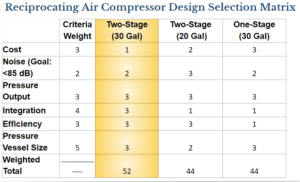
Once we had researched the different types of air compressors, we were able to narrow down our design to a certain type of air compressor. To do this, we thought about various design constraints, goals, conditions, etc. to be able to decide upon a type. This process can be seen in our design matrix presented below.


Design selection matrix for Compressor
(Key: 1- worst and 5- best)
As it is shown in the design matrix, we narrowed down our final design choice to the two-stage air compressor, with a 30-gallon tank. We determined that within the bounds of our project based on our budget constraints, the reciprocating/piston air compressor would be best, as the rotary screw and scroll would be outside of our budget. Between the single and two stage air reciprocating compressor, the cost difference is not that drastic so the benefits of the two stage in comparison outweigh the increase in price relative to the single stage compressor. Additionally, we decided on the 30-gallon compressor rather than the 20-gallon since the costs between these were also not super substantial so we made the decision to get the 30-gallon to be able to run the compressor 50% longer. We can then scale up our model based on the pressure vessel size and get the same results for different sized vessels, as if we did indeed have a much larger tank. A comparison of the information of various air compressors that we considered can be seen in the table below.
We were able to finalize which 30-gallon two-stage compressor we thought was best suited for our project, which was this Campbell Hausfeld air compressor. Information on how we initially planned to test our system can be found below.
Model Scoping:
As stated earlier, one of the main goals of our project is to analyze the performance of the overall system. This can be done through analyzing each of the subsystems individually and then combining the results as a whole.
The compressor’s overall performance can be assessed by calculating its mechanical efficiency. Mechanical efficiency is a non-dimensional quantity that measures the effectiveness of a system in converting input power to output power. For our calculations, we are going to use low fidelity modeling, treating the system as a black box (open system). A black box is a system which can be viewed solely by inputs and outputs, without having any information on its internal functions. In reality, a compressor would be treated as a closed system since it would be looking at it in terms of being a combination of two piston-cylinders. There are no physical mass exchanges within a piston cylinder, leading to it being treated as a closed system. Mathematically, it is possible to use this model and calculate the mechanical efficiency. However we experienced a lot of difficulty with this model when we have to validate it through collection of physical data, since we do not have the capability to collect the required data from the piston cylinders. Therefore, we have decided to model it as an open system, which only require the collection of input and output data which can be easily measured.
For an air compressor, the input power would be the rate of work done by the motor and the output would be the rate of work done by the air. The mechanical efficiency of our compressor can be expressed with the following equation:

The motor power would be the power when the motor is running at its full capacity. According to the specification sheet of our purchased turbine, this value is 2 HP. As for the air power, we can calculate this using the first law of thermodynamics which is presented in the equation below:
![]()
where W is the air power output, Q is the heat transfer rate by air, m is the mass flow rate of air, h is the change in enthalpy, KE is change in kinetic energy, and PE is the change in potential energy. W and PE cancel to zero, because we are assuming that our system is adiabatic and there is no change in potential energy. This leaves us with the following equation:
![]()
The mass flow rate can be calculated using the relationship of volumetric flow rate and the cross sectional area of the copper tubing. The following relationship is provided below
![]()
where ∀ is the volumetric flow rate, A is the cross sectional area of the tube, and row is the density of the air.
The change in enthalpy can be calculated with the following equation:
![]()
where cp is the specific heat capacity of air, Tout is the outlet temperature of the air, and Tin is the inlet temperature of the air. Inlet temperature is the temperature at which air is sucked into the compressor and outlet temperature is the temperature of the air that is coming out of the high pressure piston chamber.
Kinetic energy is calculated using the velocity relationship: KE = (1/2)v^(2). Where v is the velocity of the air through the copper tubing.
We now have all of the pieces to get us the respective air power output W, and consequently the efficiency.
Model Predictions:
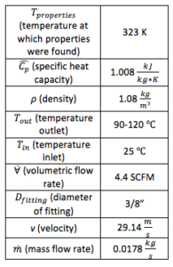
The table below provides the values of the physical properties that we initially used for our preliminary calculations:

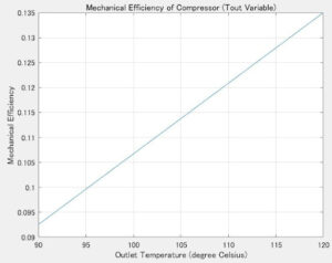
The main variables of our calculations are volumetric flow rate and the outlet temperature. We fixed the volumetric flow rate because we assumed that the value provided in the specification sheet was accurate, and the range of outlet temperatures was estimated.
We performed these calculations on Matlab and obtained the following prediction results:

Sources:
- “Industrial Air Compressors,” 01-Oct-2021. [Online]. Available:
https://www.compressedairsystems.com/industrial-air-compressors-for-sale/.
- “Compair L series airend training video,” YouTube, 24-May-2016. [Online]. Available:
https://www.youtube.com/watch?v=cmL6HEjE4nc.
- “Rotary Screw Compressor Technology explained,” 2021. [Online]. Available:
https://www.compair.com/en-pk/technologies/screw-compressor. [Accessed:
30-Oct-2021].
- “Reciprocating compressor C series – animation | Howden,” YouTube, 20-Jun-2017. [Online].
Available: https://www.youtube.com/watch?v=owNOdUBL37U.
- “Reciprocating Air Compressors: The titus company,” Compressed Air and Gas Systems,
11-Jun-2021. [Online]. Available:
https://www.titusco.com/equipment/compressors/reciprocating-compressors/.
