Concept Selection
Energy storage rose out of a need to stock up energy during low demand time periods to better accommodate needs during high demand periods.
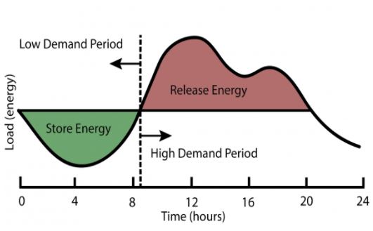
Figure 1 : Daily Energy Storage and Load Leveling. [7]
This problem is not recent, hence it is not surprising that various energy storage solutions have been developed throughout the years. Many solutions are already deployed, with CAES being one of them.
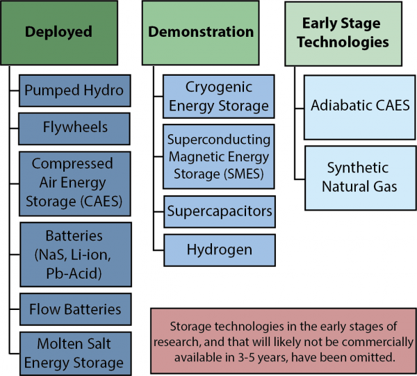
Figure 2: U.S. Grid Energy Storage [7]
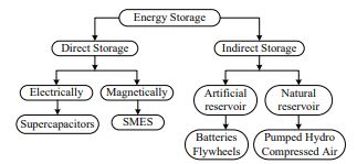
Figure 3 : Classification of Energy Storage. [7]
First, it is important to review the 3-4 current main energy storage systems.
1.Pumped Hydroelectric Storage (PHS)
- PHS systems generate electrical energy from kinetic energy by pumping water from a low to high reservoir. By releasing water through a hydroelectric turbine, electricity is generated.
- 95% of energy storage is PHS
2. Advanced Battery Energy Storage (ABES)
- Batteries store electrical energy as chemical energy. In general, the electrolyte in batteries allows for ions to flow between two electrodes and this induces the flow of electrical charge in the form of electricity.
3. Flywheel Energy Storage (FES)
- Flywheels are mechanical devices which use the conservation of angular momentum to store rotational energy. It stores kinetic energy by spinning a rotor in a low-friction enclosure. The rotor changes speed to shift energy to or from the grid.
- Flywheels are more so used for power management rather than energy storage.
4. Compressed Air Energy Storage (CAES)
- In simple terms, compressed air energy storage is a method of storing energy in the form of compressed air in a sealed enclosure for use later. Typically industrial CAES stores energy in underground caverns in the form of pressurized air that can be heated and expanded to drive a generator.
- This vessel can range from geological reserves to man-made pressure vessels and the energy can be stored for long periods of time.
As of now, the most dominant energy storage system is Pumped-storage hydropower (PSH). It accounts for 95% of the utility scale energy storage of the nation. Hydropower itself takes up 15.8% of the entire energy generation and that is also roughly 60% of all renewable sources [1] [2]. To store energy, water is pumped to a higher elevation storage (dam) using energy resources during low cost hours. When electricity is needed, the stored water is released and runs through an electrical turbine. This system has great advantages; being very cheap compared to other energy storage systems and having an overall mechanical efficiency rate of 80%. However, it is very unlikely that hydro power will remain the most popular renewable energy production in the future. The production of this facility roughly takes 3-5 years which is a long term investment. Time is a crucial factor to many investors because markets are constantly fluctuating and changing nowadays. The plant itself causes severe impact and damage on wildlife, important natural ground and residential areas. [3]
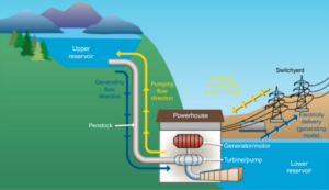
Figure 1: Pumped hydro stores potential energy in water at different elevations [1]
Electromechanical battery storage systems have seen recent growth since 2013 and even more rapid growth in years since due to significant price declines. Lithium-Ion batteries are the current market leader with 80% market share. Batteries have high round-trip efficiencies around 81-87% and have a total life of 10-15 years. It is probably the most commercially applicable energy storage system as there are already many cases of implementation across the world. Here are some examples [1]:
- The pairing of Lithium-ion batteries and solar panels are frequently used in developing countries for rural electrification.
- Battery storage facilities built by Tesla can provide 70 MW of power, enough to power 20000 houses in 4 hours.
Despite its incredible performance, batteries suffer from a number of drawbacks that limit their application to grid-scale energy storage. One is the limited supply of materials to produce Lithium Ion Batteries. Lithium-Ion batteries require rare earth metals that are very scarce and many question whether there are enough reserves for scaling up batteries. Another is the end use of these batteries. Most batteries made in the present are not designed to be recycled and this will be a large issue in the future [4]. Countries such as China are setting regulations to require recycling of batteries, but recycling is a very hazardous process due to batteries having a very complicated structure.
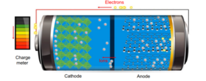
Figure 2: Solid State batteries generate electric charge by ion movement between electrodes [1]
Hydropower storage and Lithium Ion Battery storage both excel in certain areas such as power output and implementation cost when compared to CAES. However CAES has the lowest environmental impact and we believe that this is a crucial factor to our design. Using renewables directly relates to sustainability, so it is very important to consider the lifecycle of a system from production to its end use.
| Hydropower | Lithium Ion | CAES | |
| Power Output
(1 is highest) |
1 | 3 | 2 |
| Implementation Cost
(1 is cheapest) |
3 | 1 | 2 |
| Life Cycle
(1 is least impact) |
2 | 3 | 1 |
Table 1: Attribute Ranking of Three Mainstream Energy Storages
Why not Flywheel Energy Storage Systems?
As discussed before, Flywheel Energy Storage Systems (FESS) store kinetic energy by use of a rotor. Flywheels were one of the energy storage systems that we initially considered due to some of the benefits that they would provide, such as their high efficiency and their quick energy extraction process. However, these systems are not good for larger-scale energy storage systems due to their limited energy storage time, which is around only 15 minutes. Due to the issue that we are trying to solve, which is being able to store enough energy to supply the grid at all times of the day with renewable energy, we would need much longer store times than this to achieve this goal. This causes FESS to be more applicable for smaller scale problems [8].
Why did we consider Compressed Air Energy Storage (CAES)?
When comparing various energy storage methods, it quickly became clear that CAES is one of the cleanest and most cost effective forms of energy storage. As seen in the tables below taken from the international journal of engineering, CAES appears to be a reliable long term energy storage that has minimal impact on the surrounding environment. It contains the potential to become financially – sensible when taken into account that it has relatively low installation, maintenance, and fuel costs if implemented. Despite all the positives, it is difficult to store compressed air which is one of the reasons why pumped hydro far outweighs CAES in deployment. Hence, we thought it would be interesting to figure out the feasibility and difficulty of charging and discharging compressed air from a nano scale and hopefully come to an insightful conclusion as to whether this solution can become a black horse in the energy storage market when considering it’s efficiency, scalability, and economical feasibility. [7].
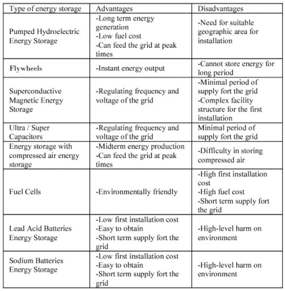
Table 2.1: Comparisons of Pros and Cons of Various Leading Energy Storage Methods [9]
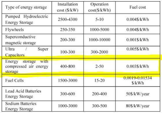
Table 2.2: Comparison of Costs by Energy Storage Type [9]
Summary of Concept Selection for CAES Subsystems
In a compressed air energy storage system, there are two main power states (charging and discharging). Usually, compressed air energy storages are looked down upon due to their relatively low energy efficiencies compared to other modes of storage. Hence, an idea struck. To what extent is it possible to improve round-trip efficiency by optimizing design stats in the various subsystems?
A ) Compressor
Considering that this project was done in school, safety and time was a priority so the idea was to purchase a compressor rather than to build one.
Between rotary screw compressor, single stage reciprocating piston compressor, and two-stage reciprocating piston compressor, the latter was chosen for its high efficiency. A 30 gallon, two stage compressor was chosen for its high efficiency, high pressure output, and financially competitive attributes. A large tank was chosen over a small tank because it has longer run times which allows for more energy storage during off-peak hours.
Compressor Design Considerations
B) Heat Exchanger
In order to capture the heat of compression to use later in warming up the air discharged from the pressure vessel, we know that by the law of thermodynamics, hotter air generally can do more work than cold air which is expected to improve system efficiency. This gave rise to the idea of adding a series of heat exchangers to ducts carrying the hot pressurized air.
The heat exchanger concept selection stems from the following questions:
-
-
- What is a relatively optimal way to effectively capture the heat of compression to improve overall round-trip efficiency and maximize energy transfer to the discharged pressurized air?
- To what extent does the use of thermal paste, solder or welding impact the effectiveness of this energy exchange?
- How will the method by which the duct will be wrapped (along the duct vs. coiled about) impact thermal resistance and surface area exposed to heat exchange?
-
Based on various heat exchanger calculations, it was determined that a heat exchanger with ⅜ – ½ inch copper tubing adhered via welding to the outlet air pipe is able to create a situation with relatively low thermal resistance, thermally conductive advantages, and adequate surface area contact for optimal heat transfer.
Heat Exchanger Design Considerations
C) Expander / Generator
Considering our stakeholders are powergrid and EV focused, it made sense that the aim of the power output is such that when scaled up, the CAES should be able to provide level 1 charging for electric vehicles – that is a minimum of 110 volts. In addition, the noise level of the turbine was also taken into account and was kept within safe hearing range. Although our budget cannot afford us the optimal equipment here, a turbine was selected for high efficiency, relatively low noise, a fair price, and other technical considerations..
Expander/Generator Design Considerations
Why look at a nano scale and not at the utility scale?
Despite its high ability in conserving energy, utility scale facilities face practicality issues such as satisfying geographic conditions. Utility scale systems require large caverns or aquifers that would be used as a tank to store the compressed air. There aren’t many locations that satisfy these conditions, and for that reason, there are only two operating CAES systems in this world at the utility scale: Mcintosh, Alabama and Huntorf, Germany. Such practicality issues can be considered a hindrance to incentivize the development of CAES systems and a reason for its unrecognition. Therefore, our team sought for a possible solution; developing a small scale adiabatic CAES system that could override the geographic constraints and be easily integrated into our society once it is scaled up.
If our whole concept of developing a nano scale CAES system is successful, we will be able to pitch this project to the EV industry as a possible model for a fully sustainable charging station. EVs have great performance in maintaining sustainability (zero emission), but it faces a major concern of lacking in the number of charging stations. According to a report documented by Mobilyze.ai, less than 10% of households in U.S. cities have easy access to a public EV charging station [5]. Also, with the expected number of EV on US roads to reach 35 million by 2030, more than 2 million public charging stations will be required within the coming years [6].
An easy way to solve this supply shortage is to create more power plants, but this defeats the whole purpose of trying to achieve net zero. Alternatively, energy storage systems could be used to store electricity during off peak hours and account for the increase in demand. Utility scale CAES system is one way to make this possible, but there are only two of these facilities in this world as of now and creating more is very costly and unlikely. We believe that a scaled-down CAES system would be the best application for these future charging stations
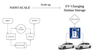
Figure 3: Scaling of EV charging [3]
References
[1] 「Fact Sheet | Energy Storage (2019) | White Papers | EESI
https://www.eesi.org/papers/view/energy-storage-2019.
[2] K. Brun, T. AllisonとR. Dennis, Thermal, Mechanical, and Hybrid Chemical Energy Storage Systems. London San Diego, CA Cambridge, MA Kidlington, Oxford: Academic Press, an imprint of Elsevier, 2021.
[3]「Examining the Pros and Cons of Hydropower」, Manufacturing.net, 9月 18, 2018. https://www.manufacturing.net/chemical-processing/article/13245967/examining-the-pros-and-cons-of-hydropower
[4] 「Millions of electric cars are coming. What happens to all the dead batteries?」 https://www.science.org/content/article/millions-electric-cars-are-coming-what-happens-all-dead-batteries
[5] T. Levin, 「President Biden hopes to build 500,000 new electric car chargers by 2030. We talked to 5 experts about how to make that happen.」, Business Insider. https://www.businessinsider.com/joe-biden-electric-vehicle-charging-stations-plan-industry-experts-2030-2021-3
[6] J. Muller, 「Biden wants 500,000 EV charging stations. Here’s where they should go」, Axios. https://www.axios.com/electric-vehicle-charging-stations-equity-1b00f7a6-f87a-4125-9bc0-82399663b345.html
[7] U.S. Grid Energy Storage Factsheet. U.S. Grid Energy Storage Factsheet | Center for Sustainable Systems. (n.d.). Retrieved December 18, 2021, from https://css.umich.edu/factsheets/us-grid-energy-storage-factsheet
[8] “Flywheel energy storage,” Planète Énergies, 07-Jun-2019. [Online]. Available: https://www.planete-energies.com/en/medias/close/flywheel-energy-storage. [Accessed: 18-Dec-2021].
[9] Reddy Salkuti, S., & Mook Jung, C. (2018). Comparative analysis of storage techniques for a grid with renewable energy sources. International Journal of Engineering & Technology, 7(3), 970. https://doi.org/10.14419/ijet.v7i3.12728
