Preliminary Concepts

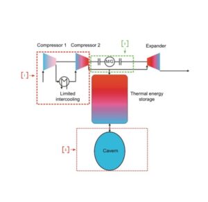
Figure 1: Process Flow Diagram of a High-Temperature ACASE plant and Potential Design Iterations [1].
Overall Cycle Explanation:
The Advanced/Adiabatic Compressed Energy Storage (A-CAES) system, assuming ideal conditions, allows for air to be compressed with a large pressure ratio and generate significant thermal energy. Subsequently, the storage process begins, and the air and generated heat are stored in compressed air and thermal energy storage units respectively. Once the air needs to be decompressed, rather than using an external heat sources to assist with the decompression, the stored thermal energy is used to re-heat the air, improving the overall efficiency of the cycle as there is no additional heat being added to the denominator of the efficiency equation [1].
[1] Due to the large-scale nature of energy plants, the high temperatures generated during air compression could physically damage the compressors. In order to decrease the damage due to these high temperatures, an intercooling phase is added to the compression phase to bring down the overall temperature. Due to our smaller scale, we do not expect the air’s temperature to reach a magnitude that could damage our compressor, therefore we would eliminate the intercooling process.
[2] A “Cavern” is a compressed energy storage unit that allows for a significant amount of compressed air to be stored. This component would be substituted for a smaller scale pressure vessel to store smaller amounts of air.
[3] Section [3] is an schematic representation of the axial configuration of an ACASE system. This configuration allows for Axial-Flow compressors and expanders to generate energy following a single-axis trajectory. Our design would substitute the axial components of the system in order to accommodate for our smaller scale.
Sources:
[1] R. Dennis, T. C. Allison, and K. Brun, Thermal, mechanical, and hybrid chemical energy storage systems. Academic Press, 2020.
