Prototype
Expansion System
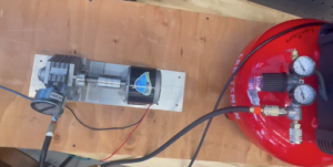
Figure 1. First prototype using a 40 psi compressor
The goal of the first test of our prototype as seen in Figure 1 was to make sure that the air motor and coupling could produce rotational shaft motion when connected to a compressor. We waited until the final mounting of the expansion system was set to run this test so that possible vibrations and alignment issues could be mediated if they presented themselves in these early tests.
- The compressor used was part of a previous project. Although it was much smaller and only had one stage of compression, the detached compressor allowed testing of the expansion system while other subteams were working with the final compressor.
- The compressor provided 40 psi of compressed air to the expansion system which converted that pressure to shaft energy successfully.
- It was also observed that minimal vibrations were caused when the shaft was operating at a steady-state and that the coupler was doing a good job of mediating any minor shaft misalignment.
A multimeter was then clamped to the generator’s exit wires to check that the shaft power was being converted to electrical energy. The multimeter read values as high as 250V. Though this value was much higher than we had expected, it made sense that without any load (ie: resistors, lightbulbs) the output voltage would be relatively high.
The experiment validated that the mechanical and electrical components of the expansion system met performance metrics (aligned and low vibrations) and successfully generated an electrical output.
Electrical Power Representation
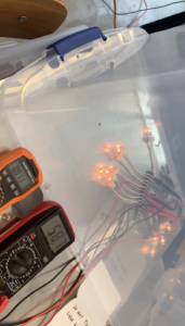
- The first electrical output prototype tested how incandescent bulbs, connected to a small compressor, reacted to compressed air input. 100W and 120V incandescent bulbs were wired to the generator and multimeter using a terminal strip. This test can be seen in Figure 2.
- At first, we connected six bulbs to the generator, as seen below. Although the multimeter was reading sizable voltage readings, 83.6V in the photo, the light bulbs were not lighting up.
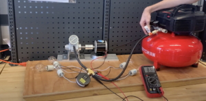
Figure 2. Test using incandescent light bulbs
-
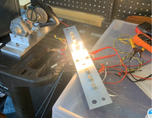
- We hypothesized that the voltage drop across the six light bulbs was too low to produce visible light, so we tested the incandescent setup with only two light bulbs attached. This can be seen below in Figure 3.
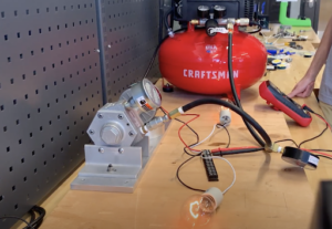
Figure 3. Test showing dimly lit incandescent bulb
-
- In this test the light bulbs lit up, proving that the light bulbs needed higher voltage drops, however, the brightest the bulbs got is pictured above. The filament only produced a dim glow at the maximum pressure inputs. From these tests, it was concluded that the incandescent bulbs would not be able to produce a steady and bright display when connected to our compressor.
- Through conversations with Adam Smith, the college’s electronics technician, and doing more research into alternative light bulbs, the next type of lightbulbs tested were 50W, 24V Halogen lights.
- Our incandescent bulb selection was primarily driven by wattage metrics. We had preliminary calculations that guided us to the decision on 100W incandescent bulbs initially, however, upon further research, we determined that our design goal of producing a bright display meant that voltage specs on bulbs should be more important when making design decisions.
- The incandescent testing demonstrated that our system sustained voltage outputs well over 50V when attached to compressed air. Because we wanted multiple bulbs in our display, choosing 24V bulbs ensured that multiple bulbs could experience brightness throughout the expansion runtime.
- The choice of halogen bulbs was also intentional. Unlike incandescent bulbs, light in halogen bulbs is produced by chemical reactions within the bulb. This means that the bulbs have lower voltage thresholds than comparable incandescent bulbs – more brightness can be achieved at lower voltage inputs. Additionally, the bulbs’ brightness scales directly with the voltage input so dimming would occur over the course of the runtime which was favorable.
- Using a power source, we first various bulb setups at varying voltages. Figure 4, shown below, is a trial of six bulbs being supplied with 61V of power.
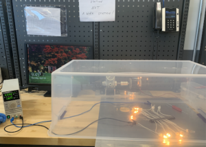
Figure 4. Trial of six halogen bulbs
-
- This trial generated much more brightness than incandescent trails at higher voltages. Already it was clear that the halogens bulbs would be much more successful at displaying power generation than the incandescent bulbs.
- The halogen bulbs were then connected to the whole system, the two-stage compressor with a heat exchanger, to see if comparable brightness was achieved when implemented into the overall design. The expansion shaft system was connected directly to the output of the compressor-heat exchanger system. Two multimeters were additionally connected to read output voltage and current values, which will be discussed further in the results and analysis section.
The bulbs successfully lit up during the system’s discharging process which verified successful full-system integration. Various tests at different compressor output pressures and different numbers of connected light bulbs were performed to better understand how the light display could be optimized for system demonstrations. Below are photos from the various tests done.
Heat Exchanger System
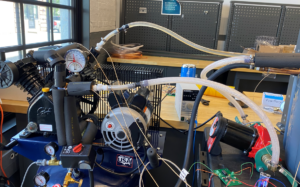
Figure 1: Insulated Heat Exchanger System
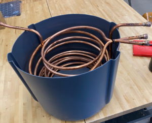
Figure 2: Thermal Energy Vessel and Heat Exchanger System
We settled on copper tubing as the material for the heat exchanger to carry our heat transfer fluids, water and air. We used around 75 feet of this tubing to create essentially 3 different heat exchangers. One representing the heat exchange occurring between the air stream from the compressor and the water in our tubing; two representing the heat exchange between the water in our thermal energy storage tank (Figure 2) and the water in our tubing; and three representing the heat exchange between the water in the thermal energy tank and compressor air being discharged. The first heat exchange process (Figure 1) is insulated to minimize heat loss.
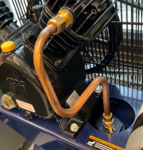
Figure 3: Shop Created Tubing Carrying Air Entering the Tank
The compressor heat exchanger, built with significant help from the shop, features soldered connections that allowed us to place new copper tubing closely around the exposed sections of the copper coils from the compressor. We also removed the copper tubing going into the tank built by the compressor manufacturer (Figure 3) so that we could recreate the tubing design and make it easier for us to capture heat from this compression. To increase heat transfer, air gaps between the copper tubing were reduced with thermal paste and thermal pads. Between the compressor heat exchanger and the other heat exchange processes in the thermal tank, we used flexible tubing with quick disconnects to make it easier for us to move the prototype. The pump circulates the water through copper tubing at a flow rate of around 0.2-0.6 GPM and has flanges to stop the flow of water through the system.
Compressor System
The compressor that we purchased was the compressor prototype itself and locked our design into stone. There were not any variations that we could make to the compressor itself since we bought it directly from a retailer and would be hurting the integrity of the compressor if we tried to make variations to it and lead to safety concerns. We conducted a thorough search of the various commercial compressors and decided upon the one that best fit the constraints and goals of our project. We did not create any simulations and/or software models to decide on this decision since it would not have been super beneficial in our design decision. Based on our analysis, the mechanical efficiency is dependent on the flow rate of the working fluid in the compressor, along with the inlet and outlet temperatures and pressures. The outlet temperatures and pressures would be unknown for each compressor, so to determine the mechanical efficiency, we would need to test the actual compressor itself. Once we bought the compressor, we could conduct this testing but could not do it before to determine the best compressor for our project. The compressor chosen can be seen below in Figure 1, with the link here directing you to more specific information about the specifications of the compressor.
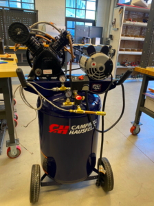
Figure 1: Campbell Hausfeld 30-gallon Two-Stage Reciprocating Compressor
Our compressor was directly integrated with the heat exchanger since a heat exchanger was being utilized to minimize the heat lost in the intercooling stage of the compressor.
- Since the intercooling stage in the compressor was most likely not going to be super efficient because of the cheap price of the compressor and the compressor being optimized for power output rather than worrying about the efficiency. The heat exchanger team decided to place copper tubing around the intercooling stage of the compressor to help extract some of the heat generated and place it in thermal storage. They had to design the copper tubing to best maximize the amount of surface area in contact with the intercooling stage so that it could extract more heat.
We also had to work with the air motor and heat exchanger teams to make sure that we could get the air from the pressure tank to the air motor.
- The air went from the pressure vessel through copper tubing into the thermal storage tank and then to the air motor. This was done to minimize the heat loss once again.
- To be able to connect the pressure vessel outlet to the heat exchanger, we needed to purchase a rubber air hose, a ¼” to ¾” air hose disconnect fitting, and ⅜” NPT fittings. Fortunately, the same fittings were needed for the connection from the heat exchanger to the air motor, so we were able to order duplicate parts and cut the air hose tube to the desired length. This process allowed us to get the air from the pressure vessel to the air motor, but also minimized the heat lost from the air of the pressure vessel.
Finally, we needed some sort of platform that would allow us to put all of these subsystems together and be moveable so that we could transport it to the senior design presentation.
- We wanted to have something that the heat exchanger could sit on so that it was on a similar height of where the compressor was to minimize head loss by the heat exchanger, while also having the air motor being able to sit on it, along with the power display.
- This led us to look at utility carts and we prioritized having pneumatic wheels and two shelves for these reasons. We found a cart on webstaurant.com that fit all of our requirements and was large enough to hold all of the elements necessary while also being able to fit through a door. The link to the specific cart we used can be seen here and the figure below (Figure 2) shows what it looks like with the compressor and heat exchanger subsystems.
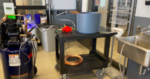
Figure 1: Utility Cart Used for Heat Exchanger and Air Motor
