Technical Concepts From Prior Courses:
In order to gain a sense of how a potential prototype could behave during testing, model development need to be completed. Physics-based modeling, where the energy storage device could be modeled as a combination of transducers, resistors, etc, are useful throughout the project. A certain component is a transducer used to convert some type of energy, whether solar or another renewable, into compressed air and into electricity. As the project progresses, it becomes clearer how the system must be modeled.
The following block diagram, taken from Sciacovelli et al, shows an Adiabatic Compressed Air Energy Storage Device:
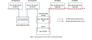
This diagram, while beyond the complexity of what our project look like, gives a sense of how we could model CAES systems. Their equations inside of the blocks were developed using assumptions from thermodynamics such as isentropic efficiencies, energy and mass balances stemming from the first law, and one-dimensional heat transfer. It’s expected that the complexities of future models need to be solved using numerical integration, likely in MATLAB software. Additionally, our system utilize concepts from other classes to help simplify and develop the model.
Thermodynamics
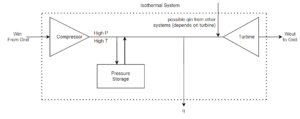
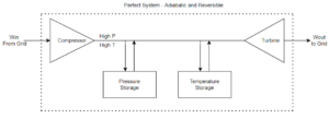
Compressed air is heated without transferring heat (adiabatic) but it’s cooled down as much as possible (isothermal) without ruining the system flow. We cannot have a perfect adiabatic and reversible system, but the goal is to have a CAES that is as adiabatic as possible. Our priorities are on the efficiencies of the compressor and turbine, and the effectiveness of the temperature storage. Heat loss from the compressor can also be considered when looking at thermal storage.
- Adiabatic: Process where heat doesn’t leave or enter the system. Our whole cycle. The compressor is in between – heat generated is stored. If stored perfectly, it can be added to the turbine cycle – higher entropy and better work
- Isothermal: Constant temperature
- First Law: Energy changes from one form to another. Conservation of Energy
- Second Law: Entropy determines whether a process is irreversible or not. (Irreversible = Heat loss to the environment).
General diagrams of 100% adiabatic and isothermal systems:
The following assumptions are made for adiabatic CAES systems:[1]
- The compressed air and exhaust gas act as ideal gasses.
- The system in any operation mode reaches a steady state.
- In compressed air and exhaust gas, no chemical or nuclear reaction and phase change exist. Potential and kinetic energy effects are negligible.
- No pressure drop occurs in the heat exchangers, recuperators, combustion chambers, and pipes.
- The temperature T0 of the reference environment is utilized as the system boundary for all exergy/entropy balances.
1) [https://aip.scitation.org/doi/full/10.1063/1.4948515]
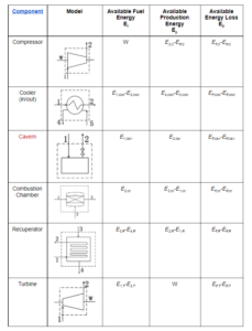
Some general equations could be modeled as:
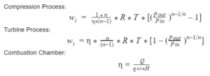
where wi is the specific power consumption of the compressor; n is the polytropic index; R is the characteristic gas constant; Pin and T are the inlet pressure and temperature of the compressor, respectively; Pout is the outlet pressure of the compressor; and η is the isentropic efficiency of the compressor. H is the lower heating value of natural gas; q is mass flow rate; Q is heat flow in the combustion chamber.
Strengths
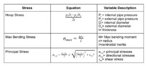
A storage device for compressed air is modeled as a pressure vessel. Pressure vessels are storage devices that hold pressures at significantly higher or lower pressures than the outside air. Plane stress is used to calculate stress at the walls of the pressure vessel. This is under the assumption that the pressure vessel is thin-walled where the radius, r, is greater than 5 times the wall thickness:
r>5t
In our application, we use a cylinder pressure vessel. This brings into account the hoop stress, which is the stress distribution perpendicular to the axis of rotation. In addition to hoop stresses, there are also longitudinal stresses and radial stresses. Radial stresses are generally neglected when a vessel is assumed to be thin-walled.
A summary of stresses in pressure vessel calculations:
