Power
The system will run off of a 100W solar panel which will charge a 12V 50 Ah lithium iron phosphate (LiFePo4) battery in the dock. The battery in the dock will sustain all the equipment on the dock including the sensors, communication systems, and user interface. The battery in the dock will also charge a 12V 10 Ah LiFePo4 battery which will power the motors and communication systems in the cart. The system will run on all DC power with the help of step-ups, step-downs, and chargers.
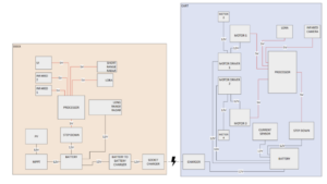
Figure 1. High-level diagram of power design for MARGE system.
i. Plug-In Charging
In the mechanical structure of the MARGE system, a pivotal component is the mating charger socket system, designed to facilitate seamless energy transfer and ensure operational safety. This system will be integrated with an off-the-shelf MPPT solar charge controller, a reliable unit responsible for managing the power supply from the solar panel to the battery. The core of this system comprises two substantial sets of metal contacts, directly connected to the battery outputs, functioning as conduits for power transmission.
To enhance the system’s reliability and safety, an additional floating center sensing pin will be incorporated, constructed from a strip of metal. This innovative feature is designed to monitor the moisture levels within the socket continuously, acting as a safeguard against potential water-induced damages and other fault conditions. Through this mechanism, the MARGE system ensures not only efficient energy utilization but also prioritizes the longevity and safety of the entire setup.
In the power segment of the project, a specialized PCB will be developed for the socketing system, central to MARGE’s efficient operation. This PCB will feature a floating center pin in the contact assembly, a critical element designed to detect moisture and other fault conditions, enhancing the system’s resilience against weather and potential tampering. It also includes current monitoring and communicates through a 3.3v i2c bus.
To ensure safety and energy efficiency, the system will not maintain a high nominal charging voltage on the contacts constantly. This prevents arcing and electrolysis of the contacts. Instead, it will employ a low standby communication mode, initiating a main power connection only through a secure handshake sequence with the cart. This approach not only conserves energy but also fortifies the system against unauthorized access and potential malfunctions, promising a secure and sustainable operation.
The dock-side component of the socket, which remains constantly energized, will be constructed using PETG via 3D printing, as illustrated in the accompanying diagrams. We will integrate a 1mm thick sheet made of either aluminum or stainless steel into this setup. The appropriate cable will be welded or crimped on the sheet metal contacts. This sheet will be precision-bent and tensioned within the mechanism to ensure a snug fit and reliable operation. The design currently displays only one of the two necessary sides for clarity. Additionally, for moisture detection, a slender strip of copper tape will be strategically placed along the socket’s center, serving as a sensitive terminal for moisture presence.
The cart-side plug will consist of a mating 3d print and bent sheet metal, and will be designed similarly with the dock-side socket.
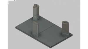
Figure 2. Preliminary Mechanical Design for Socket Side 3D Print
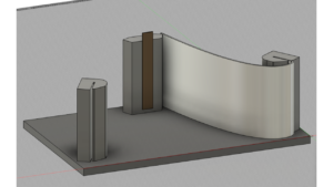
Figure 3. Setup Illustration for Socket Side 3D Print (One side)
For the dock-side, which is always energized, significant precautions will be taken to prevent the high-current charger wires from shorting or arcing. Main charging power will be supplied to the primary contacts only when the moisture-detecting floating third terminal (central copper tape) indicates dry conditions and confirms the cart side is securely docked. This is verified by testing the resistance across the main contacts with an always-on 3.3V test voltage.
Once the main contact plus is switched from the nominal 3.3v test voltage to the charging voltage supplied by the commercial Lifepo4 charger, a floating hall effect sensor will constantly monitor the charging current estimate the charge delivered, and cut off the power in case of significant overcurrent events.
For the cart side, the relay will be replaced by a MOSFET circuit that functions as a diode, allowing current only to flow into the cart battery with minimal loss. A floating hall effect sensor will oversee the charging current and approximate the amount of charge the battery receives, enabling estimation of the battery’s state of charge.
It should be noted that the system’s design emphasizes energy conservation; thus, the current sensor will not actively monitor the system’s energy use. This means that precise charge percentage estimation will be unavailable during regular operation. Reliable charge estimates will be feasible primarily when the battery undergoes significant voltage shifts indicative of full discharge or recharge cycles.
In the event that the cart’s battery is fully depleted and the system is unpowered, a backup circuit will activate the cart-side microcontroller using a 3.3V test voltage from the dock, restoring the system. This will be hardware designed to be done passively without any communication.
ii. Energy Collection and Storage in Dock
The main source of energy collection in the MARGE system is the 100W solar panel. The solar panel will be south-facing, getting around 5 peak hours of sunlight per day. The energy collected by this solar panel will run through an MPPT solar charge controller into a 12V 50Ah battery with a maximum of 20A. This 12V battery will be used as our energy storage unit in the dock. Through a DC-DC charger and the socket system, this 12V battery will charge the 12V battery on the cart supplying a constant 8A to charge the battery.
iii. Normally Closed Charging
When the cart is in the normally closed option, it sits in the center of the driveway until a recognized vehicle comes into range. In normally closed mode the cart will have to travel back to the dock to charge its battery. During setup, the owner of MARGE will be given options and decide a charging cycle for their cart. During this charging cycle, MARGE will leave the driveway to enter into the dock to be charged for 1 hour. In the case MARGE goes below 40% battery life before its scheduled charging, MARGE will leave the driveway to enter into the dock to be fully charged, staying in the dock for 1 hour. If an unrecognized vehicle appears during this charging time, MARGE will act as if it is in a normally open state and move to the center of the driveway.
The battery in the cart will have a current sensor which will detect its battery life. There will also be a current sensor in the dock charger. When the current sensor in the cart detects the cart battery to be at 40% or lower, it will have the cart be sent back to the dock to charge. When the current sensor in the dock charger detects the dock battery to be 100%, the dock battery will stop charging the cart battery. The current sensor chosen is a Hall effect current sensor. This was chosen because it is the least invasive, the most accurate, and consumes the least amount of power compared to other types of current sensors. The current sensor will output a voltage based on the input current. The input-to-output ratio is 100 mA to 1 mV.
iv. Normally Open Charging
When the cart is in the normally open option, it sits in the dock until an unrecognized vehicle comes into range. While the cart is sitting in the dock, it will be charging. The cart’s resting position in the dock will have it positioned on the charger. The cart battery will stop charging when it reaches full to optimize battery life.
v. Scheduled Charging
When the cart is in the scheduled option, it sits in the driveway for a set amount of time, moving when a recognized vehicle comes into range. During setup, the owner of MARGE will decide on a schedule for their cart. This schedule must account for the time MARGE needs to charge. During this charging time, MARGE will leave the driveway to enter into the dock to be charged for 1 hour or until fully charged. If an unrecognized vehicle appears during this charging time, MARGE will act as if it is in a normally open state and move to the center of the driveway.
Same as the normally closed mode, if the current sensor detects the cart battery to be at 40% or lower, the cart will be sent back to the dock to charge.
Sensing
To support Navigation as described in section 4f, the cart will be able to sense IR Beacons at a range of 10ft via the implementation of an IR Camera
To facilitate the function of detecting incoming and outgoing unrecognized vehicles radar sensors will be implemented. The two radar sensors that have been selected are the OmniPreSense OPS243-A Doppler Radar Sensor, and the InnoSenT GmbH 80.00000062. They will perform the function of detecting a vehicle entering or leaving the roadway, these sensors have been selected to perform one role each.
The OPS243-A Doppler Radar Sensor has a detection range of over 300ft which facilitates the designated set back distance for normally open mode in order to detect incoming vehicles. Considering the entering vehicle is expected to be moving at 10 miles per hour, it will take 20 seconds to reach the marge system. Within said 20 seconds, the Cart, which is moving at a little over a foot per second, will be able to reach its closed position. This sensor ensures that the Cart will have enough time to move.
The InnoSenT GmbH 80.00000062 fulfills the shorter-range role of detecting an outgoing vehicle. Considering the less demanding task the InnoSenT GmbH 80.00000062 has been selected for its lower range, to reduce false positives, and its lower price, to lower the cost of the MARGE system as a whole.
Microprocessor
In order to facilitate the logical control of the MARGE system several Raspberry Pico H’s will be implemented. The Raspberry Pico H was chosen as the microcontroller within the Dock, Cart, Clicker, and Remote control. The Pico H operates on a real-time operating system, which facilitates faster interrupt times, which will be crucial for the MARGE system to react to environmental interrupts such as LoRa Communications or Radar detections. In addition, the Pico can address all the wired communication that the MARGE system will use: UART, I2C, GPIO Digital ports, and GPIO Analog ports.
Communication
Figure 4. High-level diagram of Connection design for Dock
Figure 5. High-level diagram of Connection design for Cart
Lora is a chirp spread spectrum (CSS) modulation technique optimized for low power while providing functionality for trade-offs between data rate and sensitivity. These tradeoffs are determined by: bandwidth, spreading factor, and coding rate. Bandwidth specifies the size of each frequency band which can improve data rate but decrease sensitivity. The spreading factor controls how many symbols each bit of payload data is spread across a sampling period. Higher spreading factors decrease data rate but increase sensitivity. The coding rate is the number of error-correcting bits added to each payload which can prevent packages from being dropped in high noise environments but decreases data rate.
In this project, Lora will be utilized to provide long-range radio communication between the different components of our project. Each of these components: The Dock, Cart, Remote, and Clicker will contain a uniform board that will provide long-range radio functionality. Our network model will follow a star topology with the Dock at the center and every device shall relay packets through the Dock to maintain the system state. The specific data that will be flowing through the system is yet to be determined.
Figure 6: Network topology to be implemented
The board we will be designing will contain several components including a SX1276 LoRa Connect Transceiver from Semtech, a linear voltage regulator, a crystal oscillator with its resonant frequency at 32 Mhz, a Raspberry Pi Pico, and an RF switch linking the transceiver module and the SMA connector for an antenna.
The first component on the board is the SX1276 transceiver chip. This chip performs the LoRa modulation through a component called a modem and communicates with the onboard MCU through 6 GPIO ports and an SPI interface which needs 4 ports to operate. The transceiver has several different modes of operation, however, for this project, we will be implementing the chip in Packet Mode. In Packet Mode, the 6 GPIO ports will be used to give status information to the MCU, while the SPI interface will be used to change configurations on the device and transmit/receive data from the transceiver FIFO. The onboard MCU shall have firmware implementing an SPI driver and 6 open GPIO ports to decode and encode messages to the LoRa modem and shall communicate with the higher-level microcontroller through a UART port. The communication through the UART port shall be done through an API. Publicly available source code will be used as a guide for developing this API.
Figure 7 Proposed Circuit Block Diagram
The bandpass filter between the transceiver and the RF switch shall be designed in MATLAB and implemented as an LC network centered at the transceiver’s center frequency of 915 MHz. Between the RF switch and the antenna will be an L network to provide additional matching if necessary. The RF switch will be enabled and disabled by the MCU for improved power conservation.
Inter-board Wired communications utilize I2C and UART. UART is a serial communication protocol that was studied in the embedded systems course. It enables full duplex communication, i.e. two devices connected via UART can send data in both directions simultaneously. UART will connect the three LoRa chips to their respective microcontroller. I2C will be utilized to connect the remaining sensors to their respective microcontrollers. IC is chosen for these connections as it functions via a bus, which permits several sensors to communicate with the microcontroller on shared GPIO ports. In this way, I2C limits the potential risk of an insufficient quantity of GPIO ports. The remaining analog and digital GPIO ports will be used to communicate with devices that do not require serial communication, such as MOSFETs or current sensors.
In order to facilitate communication between the MARGE system and the user, a user interface has been developed. The status of MARGE will be communicated to the user via a 4×20 character transflective screen. The screen will concisely describe the current status of the MARGE system and display the options a user has to work through. A transflective display was selected because it will be visible under direct sunlight and MARGE will operate outside. The user will be able to communicate with the MARGE system through five buttons associated with the user interface; these five weather-proof push buttons will navigate through the user interface as described in the preliminary operation manual.
Movement
The cart will utilize four motors, two on the front wheels and two on the back wheels, allowing for more precise turning. The motors that will be used are the DFRobot FIT0186 12 Volt DC Motor. The wheels will be 6 inches in diameter and will add around 3 inches to the total height. The motors have an RPM of 251 and the wheels have an RPM of 41.8 which can be found through the drivetrain transmission ratio of 6. With 6-inch wheels, the cart can move with a load of 6 pounds per motor at 0.747 miles per hour or 1.1 feet per second with a torque of 12.5-foot pounds.
A set of two motor driver boards will be used to drive the four motors. Each motor driver board will have two H-bridges which will drive one side of the cart (ie. left or right). The driver will take one PWM signal and one direction signal from the processor to drive the motors accordingly via the H-bridges. Each pair of motors on a side will turn in the same direction and speed. This will allow the cart to move in the necessary direction to go either to the center of the driveway or back to the dock.
Navigation
For cart navigation, there are two aspects, the infrared tracking camera and the movement and orientation of the motors themselves.
The motors are set up in two pairs, the right and the left. The difference between the two pairs is their motor inputs. The different inputs on each side of the cart will allow for a combination of regenerative steering where both pairs of motors move in the same direction, and neutral steering where one pair stops or rotates in the opposite direction of the other pair. The cart will know whether or not to activate neutral steering based on the reading of the infrared tracking camera.
The motors will catalog the distance traveled through the use of encoders embedded in the motor itself. The integrated encoder is a quadrature hall encoder that has 64 counts per revolution of the motor shaft. That is equal to around 2797 counts per revolution of the gearbox. This will allow the cart to know where it is on the driveway based on revolutions of the encoders.
The infrared camera we will use in our design is the IR Tracking Camera model, RB-Dfr-553. The camera frame ratio is 128 x 96; Its onboard image processing analyzes the IR image data to track the X and Y positions of the four brightest IR sources in the camera’s field of view. The camera communicates via I2C, so it can easily receive updates, like altering sensitivity settings, and transmit the position of detected IR sources. By transmitting the positional information of IR sources instead of the full array of IR image data, computational load is significantly reduced for the microcontroller that the IR Camera is connected to. The IR sources that will be used along with an IR camera, are IR 940nm LED beacons. These LEDs have been selected because the camera is designed to filter to 940nm light. The wavelength filtering in combination with signal modulation filtering will ensure the IR Camera/Beacon system will work outdoors.
The two functions that the IR Camera/Beacon system will fulfill are to align the car with the dock for returning to it and to calculate the current distance between the cart and the dock. In order to calculate the cart-to-dock distance, the perceived distance between the two IR Beacons will be used. For example, when the cart and dock are ten feet apart the beacons will be ~22 pixels apart from the camera’s reading. When the cart-to-dock distance is shorter, four feet, the camera will perceive the beacons as ~55 pixels apart. Based on the pixel difference between the two beacons, the system will know how far approximately the cart is from the dock. In order to ensure that the Cart remains aligned with the Dock, the Cart will be instructed to rotate to ensure that the two beacons are equidistant from the center of the camera’s field of view. For example, if the beacons are 50 pixels apart, the cart will adjust to make sure both beacons are 25 pixels from the center of the camera’s field of view.
Structure
The MARGE system will be made up of four separate units, the dock, the ramp, the cart, and a solar panel mount. The cart, dock, and ramp will both be made of a lightweight, durable, and weather-resistant material. Both the dock and the cart will have internal structures to allow for a multi-leveled stack design to efficiently store all of the internal components. The dock’s dimensions will be 1.5 ft x 1.5 ft x 3 ft, weigh less than fifty pounds, and will have the ramp lying down next to it to allow the cart to easily traverse over the difference in height between the dock and the driveway. The ramp will be made of two 1 ft x 1.5 ft PVC sheets, and walls that will guide the cart to the charging port on the dock. The cart’s dimensions will be 1 ft x 1 ft x 2 ft and have a pyramid-like shape that will add a 3” of height onto the cart which will make it more noticeable to cars attempting to enter the driveway. The cart will be approximately 20 lbs. The solar panel mount will be a lightweight, easy-to-move set of angle brackets with a punched hole bar. The mount will allow for the solar panel to be angled at whichever degree the user chooses and will be light enough to allow the user to pick it up and move it to where they need it.
Below are two sets of Fusion drawings showing the design for both the cart and the dock. The first set of drawings shows the different views of the design of the cart. The second set of drawings details the look and measurements of the design of the dock.
Figure 8: Initial cart design
Our cart design is a 12” x 12” x 24” rectangle that has a pyramid structure placed on top that adds about another 3” in height and has the same dimensions as the cart for its width and length. The front of the cart consists of the charging prongs that will plug into the dock’s charging port as well as an IR camera that will be reading off of the array of LEDs on the Dock that will help guide the cart back to charge. The top of the cart has an antenna that will be sticking out of its center that will be communicating with radar. The back end of the Cart is fitted with a vent at the bottom of the base so that it doesn’t overheat and damage any components that are inside. The inside of the cart will have two layers which are split between the first foot of the cart and the second along with space within the pyramid. Starting from the bottom and working our way up, the Cart will be fitted with 4 motors, motor drivers, and a battery. The second layer will consist of LORA, IR sensor, Pico boards, step down, and current sensor. The entire structure will be supported with L-Channels that will help with distributing weight evenly throughout the Cart and will allow us to take off any one of the sides to work on the interior design.
Figure 9: Dock Design
Our dock design is an 18” x 18” x 3’ rectangular prism with an internal structure to provide all of the storage and structural support. The 18-inch sizing was chosen so that the dock would be slightly wider than the cart. The front of the dock will consist of a charging port for the cart to plug in to, and an array of LEDs to allow the cart to guide itself back to the dock. The right side of the dock will have the user interface, buttons to maneuver the menus, and a large vent to allow airflow to the bottom layer, which will be housing the elements that may have higher temperatures. The internal structure will be composed of three layers. The bottom layer will have heavier items such as the battery and the DC to DC charger. To combat the potential of the weight being too much for the base to support, four parallel U-channels will be placed evenly under the battery and DC to DC charger. The U-channels will run from an L-channel on one side of the dock to a different L-channel on the other side to allow the weight to be evenly distributed on the internal structure, rather than the base of the dock. The second and third layers of the dock will hold all of the boards that control the LED array, the user interface and buttons, the antenna on the roof, and all of the other miscellaneous components that will be implemented in the dock.
Figure 10: Solar Panel Mount Design
The solar panel mount consists of four 2’ slotted angle brackets, and two 2’ punched flat bars. Each triangle part of the mount has two of the slotted angle brackets and one of the punched flat bars. One of the slotted angle brackets is mounted to the solar panel, the other just lay flat on the ground. A bolt is placed through these two brackets, allowing the panel to rotate with a range of 180°. The punched flat bar is then bolted to the angle bracket laying on the ground and then bolted to the angle bracket mounted on the solar panel. To adjust the angle of tilt on the solar panel, one can remove the bolt that connects the angle bracket to the punched flat bar, and then slide the angle bracket down the punched flat bar and re-bolt the two together.
Figure 11: Ramp Design
The ramp design consists of two 18” x 12” PVC sheets held together by a piano hinge. The upper level of the ramp will be held in place by six leveling mounts so that the ramp can be adjusted to match the height of the curb or driveway. The piano hinge will allow the lower level to self-adjust its angle to match the height of the upper level. The ramp’s walls will act as a guide to allow the cart to drive straight into the charging port on the dock. The walls of the ramp are made of a more forgiving PVC sheet so that the cart can bump into them with no risk of breaking. These walls will be held in place by L-channels, and are tall enough to not allow the cart’s wheels to traverse over them.