The Smart Door Lock will secure exterior access to the home, with two access methods. The door may be remotely locked/unlocked through the SMD or RSS. There will also be a keypad located outside the door which can unlock the door. Caretakers assigned to this resident will have access to the password in case the remote unlocking is malfunctioning, or there is an emergency. Once the door closes, it will lock automatically.
![]()
Requirements:
- The door shall only unlock/lock with resident approval via the Smart Hub or from caretakers assigned to the resident.
- The system shall be able to withstand constant usage of door opening and closing.
- The system shall utilize an electronic keypad located on the outside of the door.
- The system shall utilize remote locking and unlocking via the Smart Hub.
- The keypad system shall contain a motion sensor, camera, microphone, and speaker so the resident can see and communicate with people outside the door.
- The resident shall have the option to automatically lock after it is closed by implementing a 10 second delay.
- The system shall incorporate a backup power system in case of power loss.
- The system’s primary source of power shall come from a power outlet.
- The lock shall function as a proper lock so that it stays locked if repeated attempts are made to open the door incorrectly.
Design:
See the visual diagram in the Smart Door Opener section to visualize the design conception. It will require a power connection to the same outlet which is located beneath the whiteboard. The Raspberry Pi Pico W will provide Wi-Fi capabilities for the resident to interface with the I/O components of the Smart Door Lock system via the Smart Mobile Device. The Pico will allow integration into the Home Assistant system and perform other functions such as storing the state of the door. It is important to note that only the locking system is matter compatible.
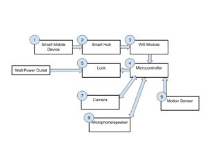
The Smart Mobile Device sends a signal to the Smart Hub. The Smart Hub sends the signal to the Wi-Fi Module on the Raspberry Pi Pico W microcontroller. The microcontroller is programmed to facilitate the function of the user based on the signal that is read. The first function is the ability to unlock and lock the door. The second function is to view the video feed from the camera and interact with the individual outside the door through the microphone and speakers. When motion is detected, the I/O devices activate, and the microcontroller sends a notification to the SMD via the Smart Hub where the user can choose to interact with said I/O devices.
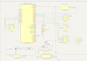
The schematic shows the inner workings of the smart door lock system. There are two power supplies which include 12V DC from the power outlet connection and 12V DC from the battery to serve as a backup power source. 12V is fed to the solenoid lock and voltage converter. The LM2596 steps the voltage down to 5V and sends that to the other devices that require it. An N-channel MOSFET is connected to the Raspberry Pi Pico W to control the solenoid lock operation. The signal from the Pico is sent using a photocoupler. The other I/O devices are also connected to the Pico based on their pin functions.
Test Plan:
Test T1 – Keypad:
Insert the incorrect code into the keypad. Then, insert the correct code into the keypad.
Pass/Fail criteria: The test passes if the lock remains closed when the incorrect code is entered, and the lock opens if the correct code is entered.
Cover Requirements: 1, 3, 8
Test T2 – Sustained Use Test:
Unlock the whiteboard and slide the whiteboard. Then, slide the whiteboard back and lock it in place. Repeat 10 times. For every time the whiteboard is locked, with a reasonable amount of force equivalent to the average individual attempting to open a locked door, attempt to slide the whiteboard.
Pass/Fail criteria: The test passes if the locking system functions correctly after repeated uses, and the lock functions as a proper lock so that it stays locked if repeated attempts
Cover Requirements: 2, 9, 8
Test T3 – SMD Interface Test:
Press the unlock button on the smart mobile device and wait 10 seconds. Then, select the lock button on the smart mobile device.
Pass/Fail criteria: The test passes if the lock completes the desired action when the resident uses the smart mobile device.
Cover Requirements: 4, 8
Test T4 – I/O Device Test:
Connect the camera, microphone, and speaker to a power source and the Raspberry Pi Pico W on a breadboard individually. Write simple code to interface with each component.
Pass/Fail criteria: The test passes if all components turn on. The camera shall display a video for 10 seconds, the motion sensor shall blink an LED when activated, a 10 second recording from the microphone shall be output, and the speaker shall output any sound that can be audibly heard.
Cover Requirements: 5, 8
Test T5 – Automatic Lock Test:
With the automatic door locking function enabled, unlock the door and wait 10 seconds.
Pass/Fail criteria: The test passes if the door locks automatically.
Cover Requirements: 6, 8
Test T6 – Backup Power Test:
Unplug the power cord and repeat test 1.
Pass/Fail criteria: The test passes if lock functions the same under the backup power supplied by the battery.
Cover Requirements: 7
