The Kick Buttons will be designed for residents who have partial mobility of their legs and can use their legs to kick objects. The kick button panel will have 5 kick buttons, allowing the resident to control the entire home automation system using them. We will be creating this kick-button system for someone who uses a wheelchair and has limited leg motor control. The buttons will be designed so that the caretaker can shift their location (by sliding) to a position that is convenient for the resident.

Figure XX: Figure title
Requirements
Initial Design Requirements:
- The kick buttons must be easy to activate, requiring minimal force to be kicked.
- They should be mounted on a raised platform that can be positioned within easy-kicking distance from the resident’s wheelchair.
- The buttons need to light up whenever they are kicked.
- The buttons must transmit data wirelessly to the connected smart mobile device.
- The power usage for the button system should not exceed 12 V or 200 mA.
- The button system should be powered with a 12V input.
After discussion with the product development team, the initial design requirements were broken down into the following technical requirements:
Technical Design Specifications:
Setup:
- The button system (5 buttons and the circuitry) shall be powered using a 12 V supply
- The 5 buttons shall be on a custom slanting mount/footrest.
Mechanical Design Requirements:

Figure XX: Figure title
- The metal strap should not hit the surface of the optical switch.
- The metal strap shall cut the laser of the optical switch once the button is pushed
- In the equilibrium position, the metal strap should not be cutting the laser of the optical switch.
- After pressed, the button shall return to the equilibrium position
- The button shall be able to hold the LED driving circuitry.
Electrical functionality:
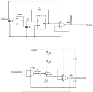
Figure XX: Figure title
- The optical switch, whose voltage is regulated by LM 7805, shall not receive more than 5.5 V.
- The current in the LED driver circuit shall not exceed 40 mA.
- The GPIO input to the microcontroller shall not be more than 3.8 V.
Individual Button Functionality:
- On pressing the button, the microcontroller shall detect a logic high.
- On pressing the button, the LEDs on the button should light up.
- On pressing the button, the microcontroller should transmit “ON_buttonNumber” message to the tablet via bluetooth. The default message for each button on the tablet should be “OFF_buttonNumber”
Overall Requirements:

Figure XX: Figure title
- The microcontroller shall compile a complete string indicating the state of each button: ON_1 OFF_2 OFF_3 OFF_4 ON_1
- The microcontroller shall transmit a complete string (as defined in the above point) over Bluetooth to the tablet.
- The system shall be responsive to rapid button presses.
General Requirements:
- The kick buttons must be easy to activate, requiring minimal force to be kicked.
- The power usage for the button system should not exceed 12 V or 200 mA.
Test Plan
Mechanical Design Requirements
- Interaction with Optical Switch Surface (T1)
- Requirement: The metal strap should not hit the surface of the optical switch.
- Test Method: Visually inspect and measure the clearance between the metal strap and the surface of the optical switch in all button positions.
- Acceptance Criteria: There should be a minimum clearance of 1 mm (to be defined as per design) between the metal strap and the optical switch surface in both pressed states.
- Test Equipment: Caliper or other precision measurement tool.
- Result: PASS/FAIL
2. Laser Interruption upon Button Press (T2)
- Requirement: The metal strap shall cut the laser of the optical switch once the button is pushed.
- Test Method: Press the button and monitor the optical switch to confirm that the laser is interrupted by the metal strap.
- Acceptance Criteria: The laser of the optical switch should be interrupted once the button is fully pressed. (See change in output from the button)
- Test Equipment: voltmeter.
- Result: PASS/FAIL
3. Laser Continuity in Equilibrium Position (T3)
- Requirement: In the equilibrium position, the metal strap should not be cutting the laser of the optical switch.
- Test Method: Set the button in its equilibrium position and check if the laser beam of the optical switch remains unblocked.
- Acceptance Criteria: In the unpressed/equilibrium state, the laser of the optical switch should not be interrupted by the metal strap. (See that output from the button is unchanged)
- Test Equipment: voltmeter.
- Result: PASS/FAIL
4. Button Return to Equilibrium Position (T4)
- Requirement: After being pressed, the button shall return to the equilibrium position.
- Test Method: Manually press the button multiple times and observe whether it reliably returns to the equilibrium position each time.
- Acceptance Criteria: The button should return to its original (equilibrium) position after release.
- Test Equipment: Manual testing, caliper for measurement if needed.
- Result: PASS/FAIL
5. LED Circuitry Accommodation (T5)
- Requirement: The button shall be able to hold the LED driving circuitry.
- Test Method: Insert the LED driving circuitry into the designated compartment within the button. Check for proper fit, alignment, and secure positioning.
- Acceptance Criteria: The LED circuitry should fit securely within the button, with no movement or obstruction.
- Test Equipment: LED driving circuitry module.
- Result: PASS/FAIL
Electrical functionality
1. Optical Switch Voltage Regulation (T6)
- Requirement: The optical switch, whose voltage is regulated by LM 7805, shall not receive more than 5.5 V.
- Test Method:
- Measure the output voltage from the LM 7805 voltage regulator to the optical switch under both idle and active states.
- Repeat the test under different load conditions and environmental variations (turning the system on or off).
- Acceptance Criteria: The voltage supplied to the optical switch should not exceed 5.5 V.
- Test Equipment: Digital multimeter or oscilloscope.
- Result: PASS/FAIL
2. LED Driver Circuit Current Limitation (T7)
- Requirement: The current in the LED driver circuit shall not exceed 40 mA.
- Test Method:
- Power the LED driver circuit and measure the current flowing through the circuit under standard and maximum operating conditions (maximize base current, i.e. i_b = 4 mA).
- Measure the current in voltage across the 300-ohm source resistor and calculate the current.
- Acceptance Criteria: The current in the LED driver circuit should be ≤ 40 mA in all tested conditions.
- Test Equipment: Digital multimeter
- Result: PASS/FAIL
3. GPIO Input Voltage Limitation to Microcontroller (T8)
- Requirement: The GPIO input to the microcontroller shall not exceed 3.8 V.
- Test Method:
- Measure the voltage at the GPIO input pin on the microcontroller in both idle and active states.
- Test under various input signal conditions to ensure stability.
- Acceptance Criteria: The voltage at the GPIO input should not exceed 3.8 V.
- Test Equipment: Digital multimeter or oscilloscope.
- Result: PASS/FAIL
Individual button Functionality:
- Microcontroller Readings (T9)
- Requirement: On pressing the button, the microcontroller shall detect a logic high.
- Test Method:
- Monitor the GPIO input pin on the microcontroller while pressing the button.
- Program the microcontroller to turn on the built-in LED if the button is pressed.
- Acceptance Criteria: The microcontroller should register a logic high signal when the button is pressed.
- Test Equipment: Oscilloscope.
- Result: PASS/FAIL
2. LED Illumination on Button Press (T10)
- Requirement: On pressing the button, the LEDs on the button should light up.
- Test Method:
- Press the button and visually confirm that the LEDs in the button turn on.
- Acceptance Criteria: The LEDs should illuminate immediately upon pressing the button and remain on while pressed.
- Test Equipment: Visual inspection.
- Result: PASS/FAIL
3. Bluetooth Message Transmission on Button Press (T11)
- Requirement: On pressing the button, the microcontroller should transmit the “ON_buttonNumber” message to the tablet via Bluetooth. The default message from each button to the tablet should be “OFF_buttonNumber.”
- Test Method:
- Pair the microcontroller with the tablet over Bluetooth.
- Observe the message log on the tablet’s receiving application or terminal to confirm that pressing the button sends an “ON_buttonNumber” message.
- Verify that the default “OFF_buttonNumber” message is sent when no buttons are pressed.
- Acceptance Criteria:
- Upon pressing the button, an “ON_buttonNumber” message is received by the tablet.
- When no buttons are pressed, the default message “OFF_buttonNumber” is received.
- Test Equipment: Tablet or computer with Bluetooth receiving capability, terminal software for message logging.
- Result: PASS/FAIL
System level integration (involves 5 buttons):
Setup:
- Power the button system (5 buttons and the circuitry) using a 12 V supply
- Place the 5 buttons on a custom mount/footrest that is comfortable to use when a person is in a wheelchair.
1. Button State Detection and String Composition (T12)
- Requirement: The microcontroller shall detect the state of each button and compose a complete string indicating whether each button is ON or OFF (e.g., “ON_1 OFF_2 OFF_3 OFF_4 ON_5”).
- Test Method:
- Press each button individually and in combinations, then observe the microcontroller’s generated string by printing the result over a serial port.
- Confirm that the microcontroller correctly updates the state for each button in the output string.
- Acceptance Criteria: The generated string accurately reflects the current state of each button in the format “ON_1 OFF_2… etc”.
- Test Equipment: USB cable for implementing serial print.
- Result: PASS/FAIL
2. Bluetooth Transmission of Button States (T13)
- Requirement: The microcontroller shall transfer the complete string indicating the state of each button (e.g., “ON_1 OFF_2 OFF_3 OFF_4 ON_5”) to a tablet via Bluetooth.
- Test Method:
- Connect the tablet to the microcontroller via Bluetooth.
- Press each button individually and in various combinations, then verify the string received on the tablet matches the current state of each button.
- Test the system under rapid button presses to confirm accuracy.
- Acceptance Criteria:
- The tablet consistently receives the correct button state string for every possible combination of button presses.
- The format matches the specified pattern (e.g., “ON_1 OFF_2 OFF_3 OFF_4 ON_5”).
- Test Equipment: Tablet or computer with Bluetooth receiving capability and logging application.
- Result: PASS/FAIL
3. Stability and Responsiveness Testing (T14)
- Requirement: The system must accurately report button states in real time under rapid button presses.
- Test Method:
- Rapidly press buttons in various sequences and observe the transmitted string on the tablet.
- Test responsiveness by pressing multiple buttons simultaneously and check for correct updates.
- Acceptance Criteria: The system should not miss any button press events or provide incorrect button states.
- Test Equipment: Logging software.
- Result: PASS/FAIL
User Utility Requirements:
1. Kick Button Activation Force (T15)
- Requirement: The kick buttons must be easy to activate, requiring minimal force to be kicked. The experiments have to be done while the person is in a wheelchair.
- Test Method:
- Ask 5 participants if the kick buttons are easy to kick, given that each of the participants is in a wheelchair.
- Acceptance Criteria: More than 90% of the people should say that kick buttons can be easily activated.
- Test Equipment: None
- Result: PASS/FAIL
2. Power Usage Limitations (T16)
- Requirement: The power usage for the button system should not exceed 12 V or 200 mA.
- Test Method:
- Connect the button system to a power supply set to a maximum of 12 V.
- Measure the current draw of the system, (by using a multimeter) under idle conditions and while buttons are being activated.
- Acceptance Criteria:
- The current draw should not exceed 200 mA under any operating condition, given that the input voltage is 12V
- Test Equipment: Adjustable power supply, digital multimeter.
Result: PASS/FAIL
Test Table
| Requirement Type | Requirement No. | T1 | T2 | T3 | T4 | T5 | T6 | T7 | T8 | T9 | T10 | T11 | T12 | T13 | T14 | T15 | T16 |
| Mechanical | 1 | X | |||||||||||||||
| Mechanical | 2 | X | |||||||||||||||
| Mechanical | 3 | X | |||||||||||||||
| Mechanical | 4 | X | |||||||||||||||
| Mechanical | 5 | X | |||||||||||||||
| Electrical | 6 | X | |||||||||||||||
| Electrical | 7 | X | |||||||||||||||
| Electrical | 8 | X | |||||||||||||||
| Individual Button | 9 | X | |||||||||||||||
| Individual Button | 10 | X | |||||||||||||||
| Individual Button | 11 | X | |||||||||||||||
| System Integration | 12 | X | |||||||||||||||
| System Integration | 13 | X | |||||||||||||||
| System Integration | 14 | X | |||||||||||||||
| User Utility | 15 | X | |||||||||||||||
| User Utility | 16 | X |
Budget
| Component | Description | Quantity | Cost per unit | Total Cost |
| Optical Switch | Omron EESX3173 | 5 | 3.57 | 17.85 |
| Switch Cable | EE-5002 | 5 | 5.61 | 28.05 |
| Voltage Regulator | L7805 | 5 | 1.46 | 7.3 |
| Op-amp | LM 324N | 10 | 0.39 | 1.95 |
| Micro | Pi Pico W | 1 | 25 | 25 |
| Protoboard | Prototype Kit | 1 | 9.99 | 9.99 |
| RGB LED | WP154A4SUREQBFZGC | 10 | 1.91 | 19.1 |
| Transistor (NPN) | BC 548 | 10 | 0.18 | 1.8 |
| Foot stand | Foot stand (kick button mount) | 1 | 200 | 200 |
| AND Gate | 74LVC1G08GV, | 10 | 0.13 | 1.3 |
| Sub Total | 312.34 | |||
| Buffer Budget for PCB | 100 | |||
| Cost for custom printing buttons | 200 | |||
| Total | 612.34 |