High Level Design
The power system design consists of three hierarchical levels: a battery, a foundation board, and functional boards that include a voltage-conversion board and H-bridge motor-control boards. You can find the the system architecture block diagram below. The battery is directly connected to the foundation board, which then distributes 12.8V to the two H-bridges and the voltage-conversion circuit. The two H-bridges are responsible for controlling the DC motor and linear actuator, while the step-down circuit provides 5V to the touch screen and Arduino boards.
The overall system design incorporates a foundation board with connectors that allow the H-bridge and step-down circuits to be easily plugged in. This design was chosen for several reasons, including the possibility of IP reuse in other projects. The foundation board also serves as an intermediate layer in the modularization of the functional boards. Furthermore, the foundation board includes three fuses to protect each of the circuits, thus reducing the required space for individual circuits.
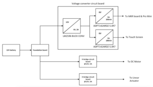
The block diagram of power system
Electrical Specifications
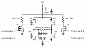
The schematic of H-bridge
- The motor-control H-bridge circuit is implemented by two power P-channel MOSFETs, two power N-channel MOSFETs, and two regular N-channel MOSFETs.
- The two regular N-channel MOSFETs, Q5 and Q6, are each connected to a 10K Ohm resistor which in turn is connected to the 12V input.
- Such a connection builds a pull up switch that draws current in 12V directly from the battery to satisfy the switching current requirement of power P-channel MOSFETs which cannot be met by Arduino’s signal output. Furthermore, a 10mF capacitor is connected in parallel with battery power inputs to decouple the voltage transmission along the wire.
The control of H-bridge is accomplished by four signal inputs as each of them controls one MOSFET. As the table below shows, Arduino signal 1 & 4 that control Q1 and Q4 forms a pair to drive the motor forward biased; Arduino signal 2 & 3 that control Q2 and Q3 forms a pair to drive the motor reverse biased.
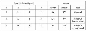
Motor & Linear actuator control guide table
B. Step-down circuits
A step-down circuit was selected to power small electronic components within the system due to its high efficiency, which conserves power from the primary battery source. The circuit operates in two stages, a voltage step-down stage from 12.8V to 6V using an LM2596 buck converter, followed by a regulation stage to 5V using two Low Dropout Regulators. A Low Dropout Regulator (LDO) is a voltage regulator that can maintain a stable output voltage with a very small input-output voltage differential and low noise, thereby reducing power dissipation and heat generation. The board provides three 5V outputs, each capable of delivering up to 200mA, with a maximum output power capacity of 3W.
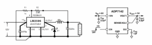
Step-down circuit from 12V to 6V (left) and step-down circuit from 6V to 5V (right)
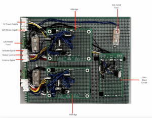
How does the final circuit board look like?