Overview
We aim for AuBi to be able to maneuver both efficiently and effectively. The drive system is made up of two motors powering the rear wheels and two castors which serve as the front wheels. The drive system is controlled by a Jetson Nano, which will send instructions to the motor controller depending on what the navigation algorithm deems necessary. The motor controller takes both the instructions and encoder signal and uses a PID algorithm to drive the motors accordingly. This is done by sending PWM and digital signals to the motor driver.
Current Research
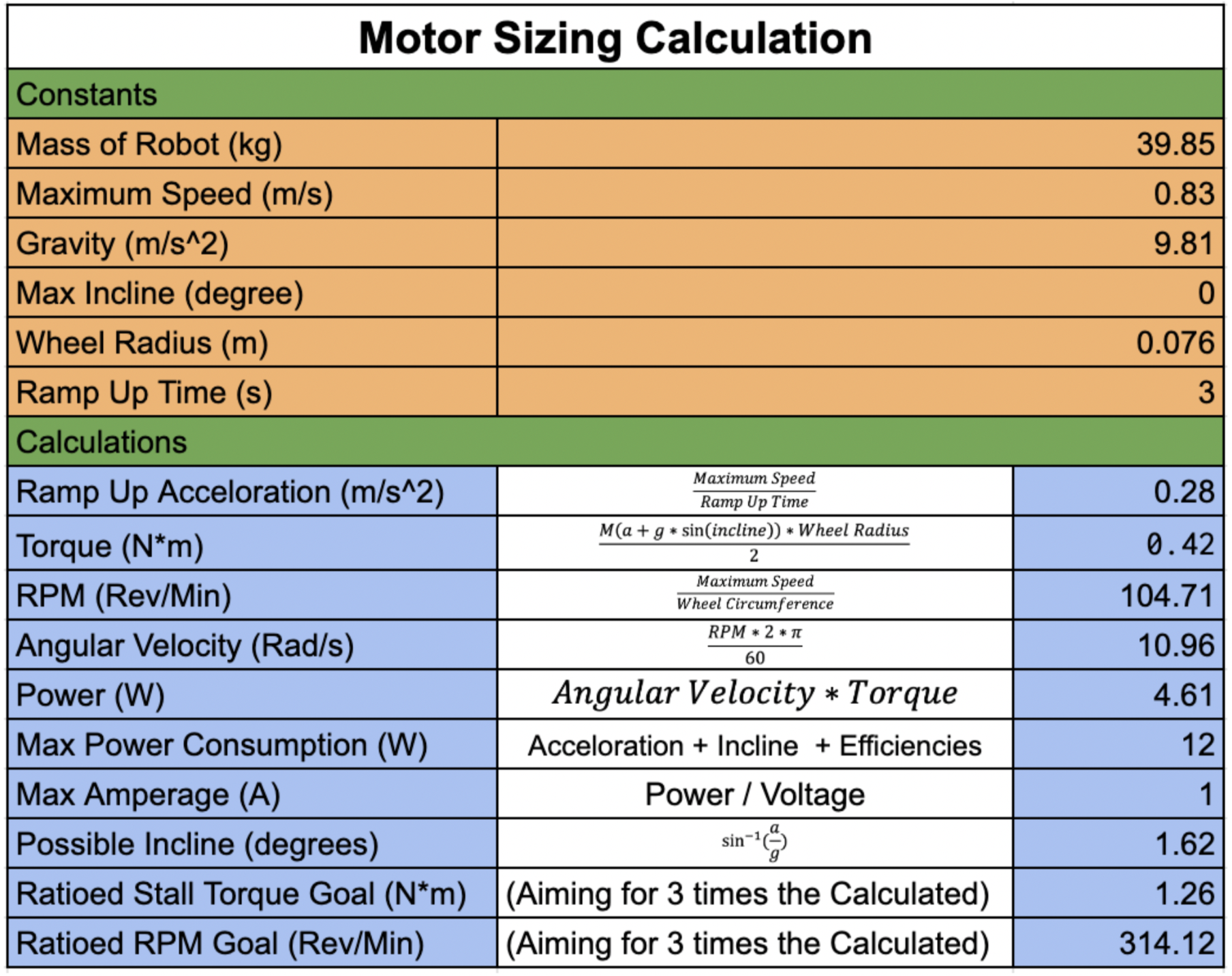
Once the standard drive system was decided upon, the next and most crucial step towards defining our drive system is what motors AuBi requires. Based upon the robot’s mass, maximum defined speed, wheel radius, and ramp up time calculations can be made to determine the best motor calculations. An acceleration of 0.28 m/s^2 will be achieved with a Torque of 0.42 N*m and RPM of 104.71 Revs/min. A good rule of thumb is to pick a motor that can achieve three times the calculated RPM and torque. This means we are looking for a motor stall torque to be 1.26 N*m and RPM of 314.12 Revs/min. The NeveRest Orbital 20 Gear Motor has a Stall Torque of 1.23 N*m and has 340 RPM. The NeveRest Orbital 20 Gear Motor also has a built in encoder which is necessary in controlling the motors
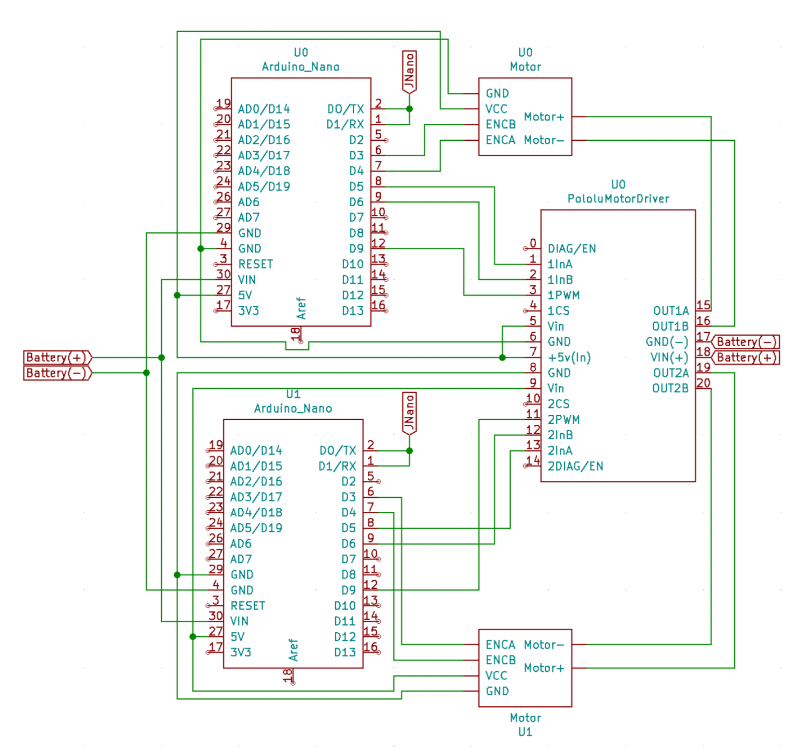
The next step is designing a way to control the motors. Using the Jetson Nano, Arduino Nanos, Pololu Dual High Current Motor Drivers, and the Neverest Orbital 20 Gearmotors a PID control system can be implemented to properly drive AuBi’s drive system. The Jetson Nano will be running ROS (Robot Operating System) which has a plethora of libraries and tools to establish the Navigation System and translate information from the encoders to instructions on where AuBi should go next. The Arduino Uno’s will act as the motor controllers and are responsible for encoder input data, instructions input data, translating inputs using PID controller and outputting PWM and digital signals to the motor driver. The Pololu Motor High Current Motor Driver is a Mosfet Dual H Bridge driver which is very efficient. A detailed schematic of the drive system can be found below.
Motor Design
Current Research
So far, the drive system is under construction and tests are being carried out. These tests include reading from the encoder, measuring position of the drive shaft, driving the motor, controlling the motor, etc. Code regarding the arduino PID controllers are being written and tested upon as well in parallel to the physical tests.
Next semester, more tests will be carried out regarding controlling the motors. Once an established PID controller seems to be working, tests regarding integrating controls from the navigation system as well as driving the physical robot will be implemented.
Literature Review
Drivetrain Systems: Descriptions and Comparisons
https://kb.vex.com/hc/en-us/articles/360035952771-Creating-a-V5-Drivetrain
There are five drive systems to choose from, each having advantages and disadvantages. The summary of each system can be found in the link above and comparisons found in the table below.
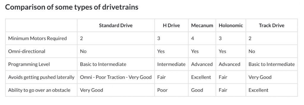
The AuBi team needed to consider a system that has 2 motors, easy to program, and versatility in moving. The Standard Drive offered us everything we were looking for.
Slipping vs Tipping
http://adaptivemap.ma.psu.edu/websites/7_friction/7-2_slipping_vs_tipping/slippingvstipping.html
The slipping vs Tipping was an important calculation to consider when designing the drive system. The frictional coefficient the wheels have to offer as well as the placement and orientation of the wheels is a major factor in whether the robot will Tip or Slip.
Omni Wheel Frictional Coefficient
Discussed above, the frictional coefficient of the wheels plays a major role in determining whether the robot will tip or slip. Linked above is the measured coefficients of different omni wheels which can give us a more accurate calculation towards whether AuBi will tip or slip.
Motor Sizing Calculations
Linked above is an article that breaks down how to calculate the size of the motors required to drive a robot taking into account mass, max speed, desired acceleration, slopes, wheel diameter, etc. This allowed us to calculate the required Torque, RPM, and Power of the motors.