Overview
We aim to keep AuBi as easy to use as possible with very little maintenance involved. For this reason, the system will charge itself by navigating to the location of a wireless charging station. The charging circuit is made up of two hand wound coils tuned to a frequency of 33.3 KHz. The transmitter is driven by a motor controller simulating an AC signal. The signal is then rectified and sent to the 12V battery on the receiving end.
Current Research
As of May 2022, a prototype wireless charger exists that can provide 0.1 A to a 12V battery. The design is shown in the block diagram below. The transmitter is dependent on a Pololu G2 High Power Motor Driver 24V13 which creates an alternating square pulse that resembles AC. When provided with the correct PWM inputs, the motor driver can output a frequency of up to 100 KHz.
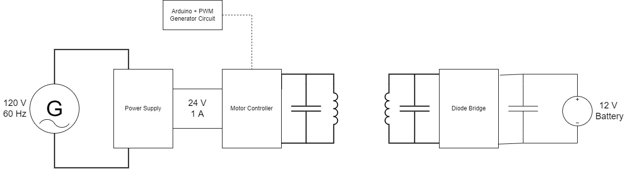
Figure 1: Block diagram for charging circuit
The motor controller requires a PWM input as described above. A typical motor controller does not allow you to change the frequency of the PWM it produces. A circuit was creates to allow for a variable frequency output. A DAC is used to supply a PLL with a voltage that controls the output frequency of that device. A D flip flop is then send to cut this frequency in half as required by the motor driver. Here is a diagram of the PWM creation circuit.
![]()
Figure 2: PWM Creation Circuit
With the transmitter circuitry in place, the motor controller now produces an output as seen below. The yellow signal is the A output and the blue signal is the B output. Note that there is a period of “coasting” in between pulses to keep from high current spikes.
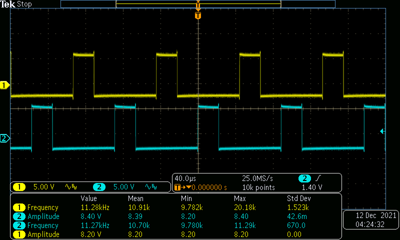
Figure 3: Motor Controller Output
At the receiver end, a diode bridge is used to convert the AC to a DC current that can be sent to the battery.
Future Research
Future work on the charging system would involve optimization. The current design is a proof of concept and only transmits about 100 mA at peak performance. This is due to a separation between the transmitter and receiver coil of about 3/8” as well as unoptimized coil characteristics.
A series of experiments could be run to determine the best coil characteristics that transmit the most power. This would involve changing the number of coil turns, the capacitor size, the inductance of the coil, the radius of the coil, and bunch more other variables.
Literature Review
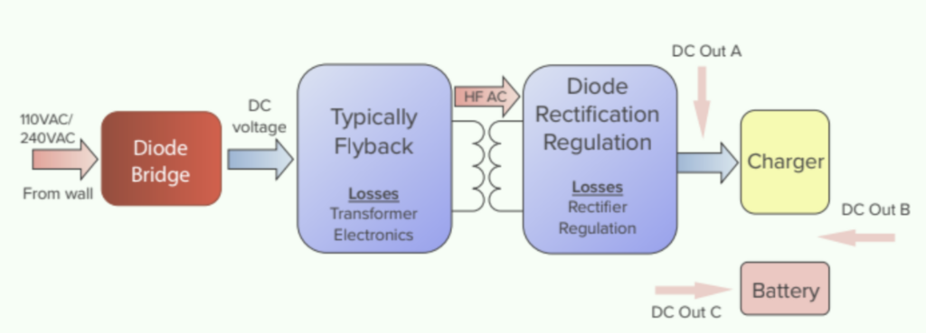
Considerations When Designing a Wireless Charging System
- Inductive vs Resonant
- Diagram for typical layout
Designing a Qi-Compliant Receiver Coil for Wireless Power Systems
https://www.mouser.com/pdfDocs/TI-Designing-a-Qi-compliant-receiver-coil.pdf
- More about Qi compliance
- Flowchart for the process of designing a coil
- Equations for number of turns
High Efficiency Power Transmission
“High Efficiency Wireless Power Transmission via Planar Spirals with Proximity Detection” Stinner Thesis 2011
- The contents of this paper will act as a basis for our design. Redesign coils, change frequency, and use H-bridge
- Details ways to localize robot based on distance from charging station
Standards for Wireless Charging Technologies
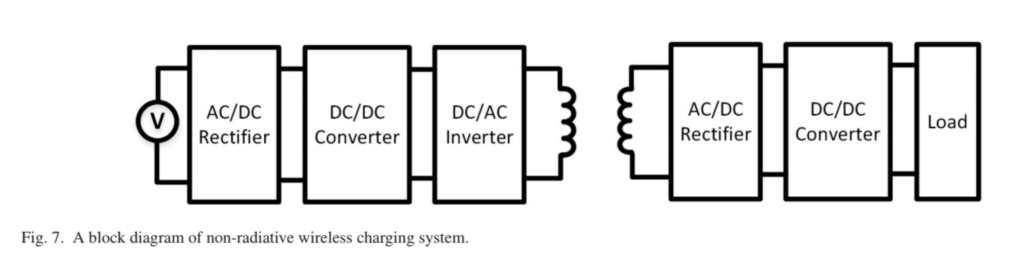
“Wireless Charging Technologies: Fundamentals, Standards, and Network Applications” IEEE Xplore
- Explains the history of wireless charging starting with the discovering of magnetic fields
- Inductive Coupling vs Magnetic Resonance Coupling vs Capacitive Coupling
- A block diagram of a wireless charging system
- Equations for analysis of electric field and efficiency
- Wireless charging standards. These rely on communication links between transmitter and receiver. Can try to be compliant if we have time.
- Applications (Not useful for us)
Planar Spiral Inductances
“Simple Accurate Expressions for Planar Spiral Inductances” IEEE
- Lists 3 methods for determining the inductance of different planar spiral shapes
- Square, Hexagon, Octagon, Circle
- Compares simulated results to physical experimentation
Power Transfer Concept
“Fast Charging a 12V Battery Using Wireless Power Transfer Concept” IEEE Xplore
Existing Solutions:
WiBotic – wireless charging company out of Seattle
Can charge many different types of batteries. Has optimization techniques.
jjPlus is similar to WiBotic