Purpose
Whether operating remotely or independently, the addition of a robotic arm elevates the impact of a robot, allowing it to transition from being a mere observer into a system that can interact with its environment and itself.
Design Objective
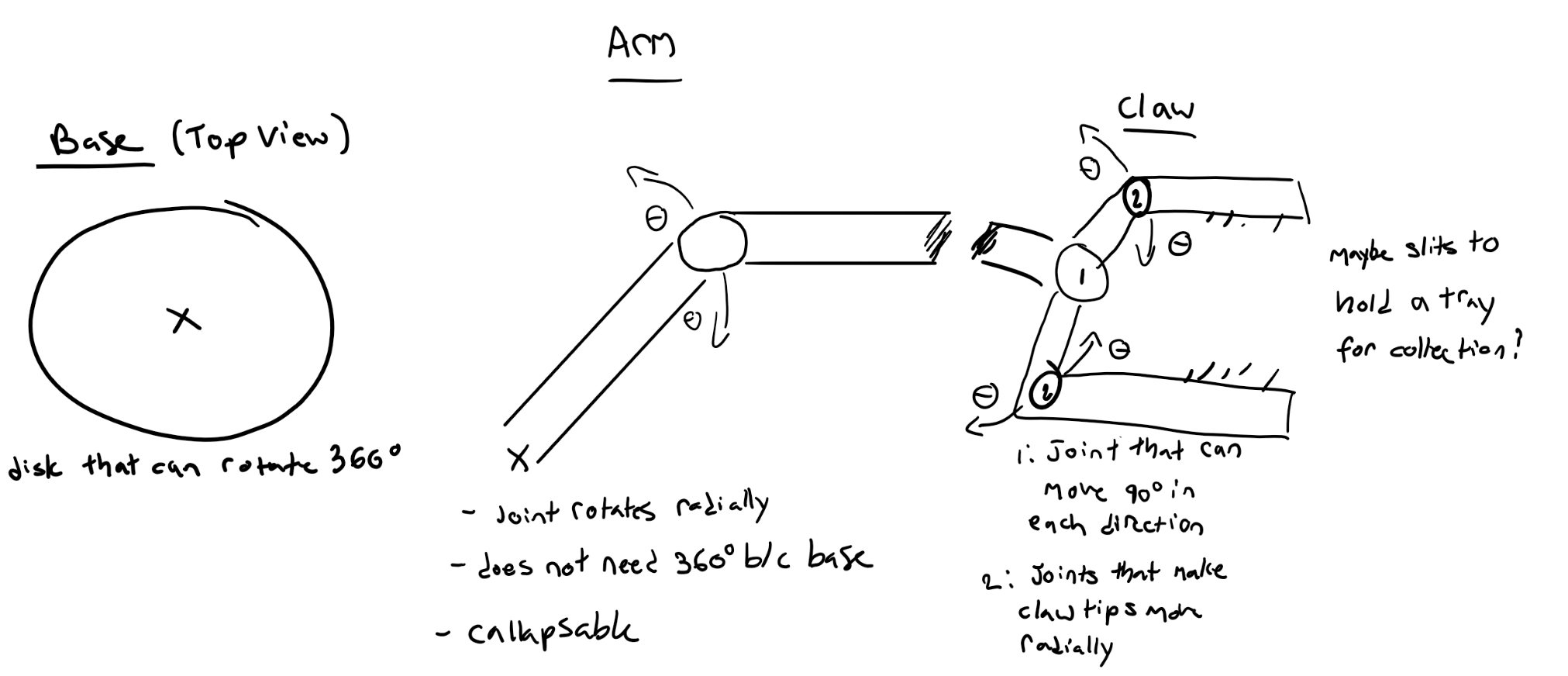
The goal of this subsystem is to enable the robot to lift, push, pull, and otherwise manipulate elements of the environment and also itself. Some basic uses will be to move debris, take samples from the environment, and access its own storage space. This functionality can be achieved via a variety of ways, including:
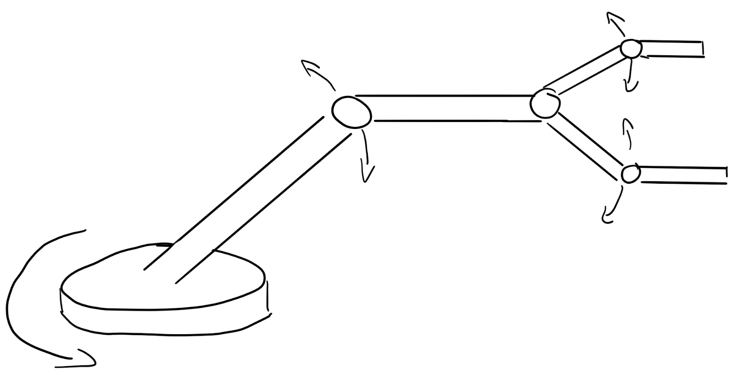
- Collapsing Arm Joint: a center joint in the arm will allow the arm to fold in on itself, allowing more mobility and compactness
- 360° Base: The base will move 360°, bypassing the need for each arm joint to be too complicated in movement (So no need for dealing with degrees of freedom)
- 3 arm joints: one at the base, one at the center, one at the claw
- 2 claw joints: allows for actual grabbing motion

A 3 joint arm with 2 claw joints.
Technical Concepts
The subfunction enabling the robot to interact with its environment, in this case, a design that would allow for the robot to be able to pick up and distribute objects, includes various concepts learned throughout the Lafayette College mechanical engineering program, such as:
- Cylindrical Directions: The joints of the arm would need to use concepts such as moving in the “theta”, “r” and “z” directions in order to achieve its movement goals.
- Polar Coordinates: If it’s decided that the base of the subsystem needs to rotate 360 degrees, polar coordinates would need to be used in order to determine the exact location the base rotates to.
- Complex 3D Free Body Diagrams: In order to correctly model the subsystem and make sure it can support the weight of an object, an understanding of 3D FBDs, as well as force distribution, needs to be known
Metrics
Constraints
Relevant Codes and Standards
- Robotic Vocabulary
- Robots and robotic devices — Coordinate systems and motion nomenclatures
- Object handling with grasp-type grippers
Next Steps
- Finding a suitable material
- Determining the location of the arm on the robot
- Seeing if the design is plausible
- Finding out how to make it suitable for operating underwater
Citations
Development of a low-cost underwater manipulator. (n.d.). Retrieved October 13, 2021, from https://dspace.mit.edu/bitstream/handle/1721.1/36303/77747979-MIT.pdf?sequence=2&isAllowed=y.
Hydra-UW (hydraulic robot arm – underwater). (n.d.). Retrieved October 13, 2021, from http://www.knrsys.com/portfolio/hydraulic-based-robot-3/.
PincherX 100 robot arm. X-Series Robotic Arm. (n.d.). Retrieved October 13, 2021, from https://www.trossenrobotics.com/pincherx-100-robot-arm.aspx?feed=Froogle&gclid=Cj0KCQjw18WKBhCUARIsAFiW7Jxe21sYuCvoC0RdvXdOunVZYiiW3q5SWUR3-JikMzvVoB5xQEeXhKsaAn10EALw_wcB.

