Purpose
Whether in service performing reconnaissance in uncharted territory or providing aid in disaster-struck environments, the ability to traverse and navigate uneven terrain can be considered an essential function for any robotic system seeking to provide high utility to its operators.
Design Objective
The primary objective of this sub-function is to be able to enable the robot to directly traverse complicated terrain. Rubble, mud, large rocks, and gaps of varying sizes seem to be the most likely obstacles that need to be cleared.
With respect to climbing, there are a series of designs that can be utilized to assist the robot with scaling obstacles and surviving falls:
- Fishhook Grippers: Ideal for use in rough surfaces such as boulders and cave walls, hundreds of fish hooks are incorporated into each of the robot’s legs and software is used as a mechanism for guiding the robot to increase in elevation (Parness, 2017).
- Microscopic Angled Hairs: Ideal for use in smooth surfaces and uses technology inspired by a gecko’s sticky feet; these microscopic angled hairs generate van Der Waals forces (atomic forces that cause stickiness) when 2 objects are in close proximity to one another. In this case, the objects in close proximity include the robot’s legs / wheels and the terrain that is being traversed. Further enhancing the microscopic angled hairs, the robot’s wheels can utilize an electrical charge to assist with clinging to walls (e.g. similar phenomenon behind your hair sticking to a balloon after you rub it on your head) (Parness, 2017).
- Robotic Arm Assist: This system allows the climbing system to be more integrated with another (a robotic arm). By placing a wheel on the arm, the arm can place itself on a surface, exerting pressure and thus raising the robot. Combined with positionable wheeled legs, this system can traverse various gaps and types of obstacles. A track design on the legs may strengthen its performance over uneven obstacles. The benefit of this design is that it reduces the complexity of a “fully legged” design (Wang, 2017).
- Segmented body: Movement capabilities on different body sections can be utilized for different purposes. For example, some body segments could be used to maintain traction to cling to the wall, while other segments could be used to lift the robot onto the obstacle (Fu Q, 2020).
- Upwards Facing EDF (Electric Ducted Fan): The robot could use an EDF, or similar object, to generate a normal force when the angle of the force of gravity is no longer sufficient to maintain a normal force to cling to the wall (Papadimitriou, 2019).
To traverse an obstacle, a potential opportunity for the robot to utilize can be partitioning its body into three components (a design that has been utilized in past robot implementations) – when approaching an obstacle, the front section can increase in length, the middle section would remain roughly static, and the rear section can shorten to allow the robot to successfully navigate over the obstacle. In addition, the speed would be reduced during the traversing period, especially for high obstacles / slippery surfaces to help maintain stability.
Original Concepts
Split Track
Deformable Wheel
Technical Concepts
Dynamics: This function seems to be deeply tied to concepts covered in physics. Free body diagrams will need to be carefully constructed to determine the location of the center of gravity for different orientations. In addition, it would be important to know whether the supports can generate the friction necessary to maintain the robot’s orientation.
Chemistry: Depending on our scale, methods of clinging to surfaces (Van der Waals, adhesion, hooks) may require some knowledge of intermolecular forces.
Metrics:
Constraints
Relevant Codes and Standards
Since this subsystem will require significant coordination with the land movement subsystem, the relevant codes and standards will overlap.
Next Steps
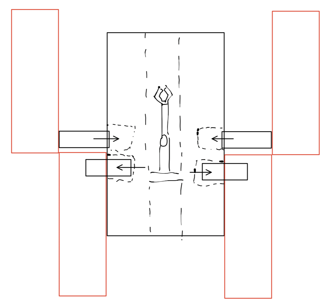
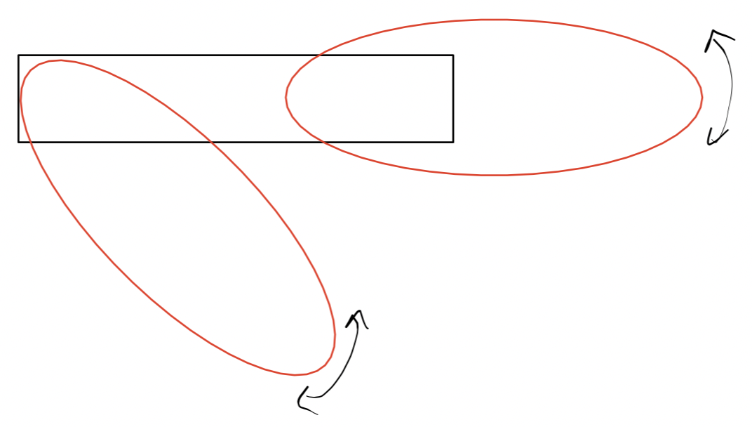
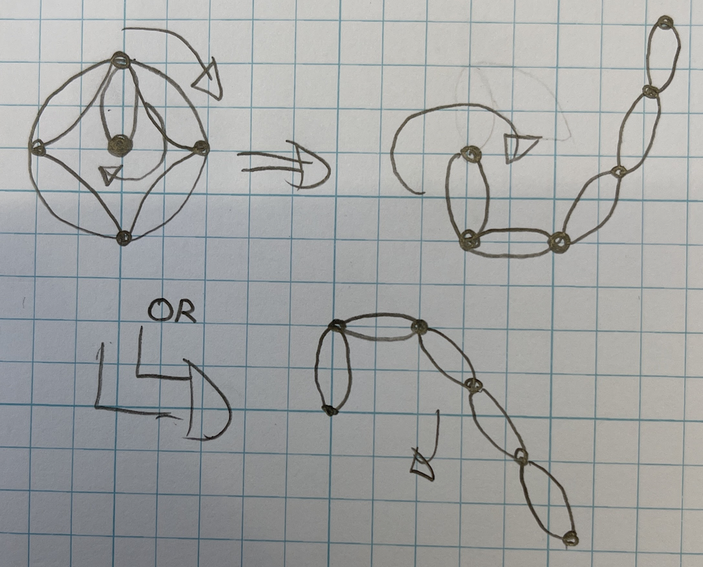
- Team to provide feedback on the designs / original concepts illustrated below, and we must iterate on the designs
- Designs must be formally implemented utilizing 3D Modeling Tools such as AutoCAD, Inventor and sub-teams must work together to finalize these designs
- Acquire a greater understanding of feedback control as this will be an integral part of enabling the robot to decide what step to take next mid-climb – take lessons from ME480 Controls
- Formally define the type of obstacles the robot should be prepared to encounter
- Coordinate with swim and land movement functions to ensure functional continuity
- Begin building and machining!
Citations
- A. Papadimitriou, G. Andrikopoulos and G. Nikolakopoulos, “Development and Control of a Differential Wall Climbing Robot based on Vortex Adhesion,” 2019 18th European Control Conference (ECC), 2019, pp. 1610-1615, doi: 10.23919/ECC.2019.8796154.
- A. Parness, N. Abcouwer, C. Fuller, N. Wiltsie, J. Nash and B. Kennedy, “LEMUR 3: A limbed climbing robot for extreme terrain mobility in space,” 2017 IEEE International Conference on Robotics and Automation (ICRA), 2017, pp. 5467-5473, doi: 10.1109/ICRA.2017.7989643.
- Bridge, Brian; Hillenbrand, C.; Schmidt, D.; Berns, K. (2008). CROMSCI: development of a climbing robot with negative pressure adhesion for inspections. Industrial Robot: An International Journal, 35(3), 228–237. doi:10.1108/01439910810868552
- Fude, Wang; Jigui, Zheng; Guifang, Yuan; Pengfei, Li; Junrui, Hou (2017). [IEEE 2017 Chinese Automation Congress (CAC) – Jinan (2017.10.20-2017.10.22)] 2017 Chinese Automation Congress (CAC) – Design and obstacle-climbing performance analysis of arm-wheeled robot based on creo and adams. , (), 7555–7559. doi:10.1109/CAC.2017.8244145
- Fu Q, Li C. (2020) Robotic modelling of snake traversing large, smooth obstacles reveals stability benefits of body compliance. R. Soc. open sci. 7: 191192. http://dx.doi.org/10.1098/rsos.191192
- Shen, Junke; Liu, Yong (2015). [IEEE 2015 IEEE International Conference on CYBER Technology in Automation, Control, and Intelligent Systems (CYBER) – Shenyang, China (2015.6.8-2015.6.12)] 2015 IEEE International Conference on Cyber Technology in Automation, Control, and Intelligent Systems (CYBER) – Design and analysis of an obstacle-crossing wall-climbing robot mechanism. , (), 2067–2072. doi:10.1109/cyber.2015.7288267


