Technical Analysis
When designing the physical implementation of this project, our goal has been to combine durability with affordability, while taking into account how the station will be used at LaFarm and where it fits into the farm’s food cycle. We were instructed by Sarah Edmonds to use treated wood materials in the construction of the station to avoid deterioration (which was a problem with the old station), and our choice of all materials used reflects this desire to build a structure that will last. There were many decisions that were influenced by wash stations developed previously (Godfrey); some of which, were GAP certified.
Construction:
The first step will be to lay out a concrete monolithic slab foundation. We were expecting to have this done by a contract worker who would be able to do so properly, but we may be able to have a professor on campus do so instead, thus avoiding some labor costs. Either way, we want this foundation to rise at least 6 (but preferably 8) inches off of the ground, and to be 10×15’ in size. Doing so will protect the lower part of the structure from moisture. Also, we want the top of the foundation to be sloped slightly as a preventative measure to keep water from pooling in the corners of the station.
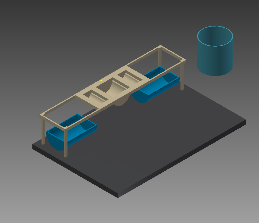
- A computer model representing the concrete monolithic foundation with the wash station components on top
While laying the concrete, we want the workers to insert lag bolts into the slab before it dries, so that when it does we can bolt the structure directly to the slab for a secure connection. This will dispel any concerns about wind moving the structure.
Next we will lay vinyl composite 1x4x8 boards along the edges of the foundation where the walls will be put up. These will function as the lower of the two layers that will form the lower sill plate. We’ve chosen vinyl composite material since this will be the part of the structure that comes directly in contact with the foundation, and therefore will be most exposed to moisture.
Next, the walls will be constructed on the ground, and then raised onto the foundation and secured together (though the builder may choose instead to simply build the walls upon the foundation). We’ve chosen a three-wall design, with two walls along the 10ft borders of the foundation and the third along the 15ft border. These walls will include, in ascending order, the upper part of the lower sill plate, the studs (spaced 16in), and the upper sill plate. We realize that not all studs will fit 16in apart, so the measurements will start at the corners for the 10ft walls (leaving the smaller space at the open end). It does not matter which side the measurement starts on the 15ft wall. All components mentioned will be 2x4x8 pressure treated boards, chosen for additional moisture and deterioration protection as well as low cost.
The corners where the 10ft and 15ft walls connect will be composed of three 2x4in studs nailed together, with each wall going off of these corners. The ends of the 10ft walls will be comprised of one additional stud to mark the end of the wall. Though the lower sill plate will consist of a pressure treated board on top of a vinyl composite board (once the walls are erected), the upper sill plate will be two pressure treated boards nailed together, with the seams staggered for added strength.
The roof will be a single-slope design, directing water to the rear of the structure (behind the 15ft wall). The construction will utilize 2x4x12 pressure-treated boards acting as cross members running the length of the roof. They will be raised on the front side (above the open wall) by a small 2ft wall constructed on top of an upper sill plate that will run between the ends of the 10ft walls, thus technically functioning as the lower sill plate for the smaller wall. The smaller wall will also have an upper sill plate (each of these sill plates will be constructed in the same manner as the upper sill plates on the 10ft and 15ft walls, with two pressure treated boards nailed together), which the cross members will be connected to after the ends have been cut to the appropriate angle (78.9 degrees). The cross members will rest on the 15ft wall on the other side, with a crow’s foot notch cut into each at the point of contact.
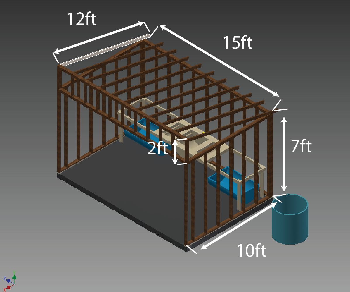
- The model now includes the framing of the walls depicted in the analysis
Finally, the 10ft and 15ft walls as well as the roof will be covered with galvanized corrugated steel. In order to fasten the corrugated panels, 1in strapping boards will run the lengths of the walls horizontally, with a vertical spacing of 1ft between each board. The corrugated panels will be fastened directly to these strapping boards, with 1-rib overlaps along the walls and 2-rip overlaps on the roof (for extra water protection). Since the corrugated panels come in 8ft lengths, a secondary row will need to be laid on the lower part of the roof. It will be fastened underneath the ends of the first row, to ensure water runs off the roof without passing through the seam. Also, the lower part of the panels covering the walls will run past the lower sill plates and overlap the concrete foundation, providing further moisture protection for the lower part of the structure.
To let a little extra light in, the triangular section above the 10ft walls will be covered in clear corrugated plastic instead of steel, and will still have the 1-rib overlap.
To provide some ventilation to the structure during the summer months, soffit paneling will be placed vertically along the 2ft roof wall, alternating between solid soffit panels and ventilated soffit panels.
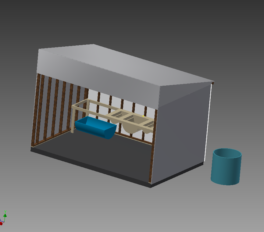
- The model now includes the final construction of the three-wall structure with the wash station inside
With the structure now complete, we must focus on the station itself. The industrial sink that will function as the wash station will be positioned in the center of the table that supports it, with two open sections on either side that will be covered in chicken wire. These open sections are where vegetables will be placed to dry. Underneath these sections will be the halves of a 55-gallon barrel, cut in half to catch the water dripping off the vegetables. The sink will also drain into these barrels, which will each be connected with PVC piping to a larger external reservoir. Collecting the water in this manner will prevent it from simply draining into the nearby stream and contaminating the stream with pesticides and other chemicals.
The design we have presented in this technical analysis describes how we believe that the engineering team should execute the construction of the structure; however, additional structural analysis is still necessary.
Water Cycle:
A key component of the wash station design is to ensure that an efficient and sustainable water cycle is established and maintained. The current Art Hendrickson irrigation system enables the commercial plots to receive drip irrigation, and delivers water throughout LaFarm to communal watering stations that can be used by any member of the LaFarm community.
The irrigation system was developed by a Lafayette faculty member, Professor David Brandes. The system uses solar panels to run a pump that extracts water from a well and feeds it to a collection container on top of a nearby hill. The water is then gravity fed to watering stations throughout LaFarm. While this system has been successful in supplying water to LaFarm, the addition of a solar powered wash station that complies with FSMA standards to the system requires modifications to its current design.
New issues that arose when attempting to meet regulatory standards included an inability to collect runoff for chemical analysis, as well as a lack of a external battery for the solar panel to ensure additional solar-powered technologies (such as a UV filter) can simultaneously run with the water pump. The new design keeps these features in mind as well as the main contexts that have most heavily influenced the decision making process. These include adhering to the social, environmental , and historical values that have shaped LaFarm and contributed to its campus-wide and community-wide impact. All in all, the development of a water cycle that can ensure a sustainable treatment of the water while ensuring access for the entire LaFarm community is paramount.
The Following figure shows the 4 main stages of water flow in our system:
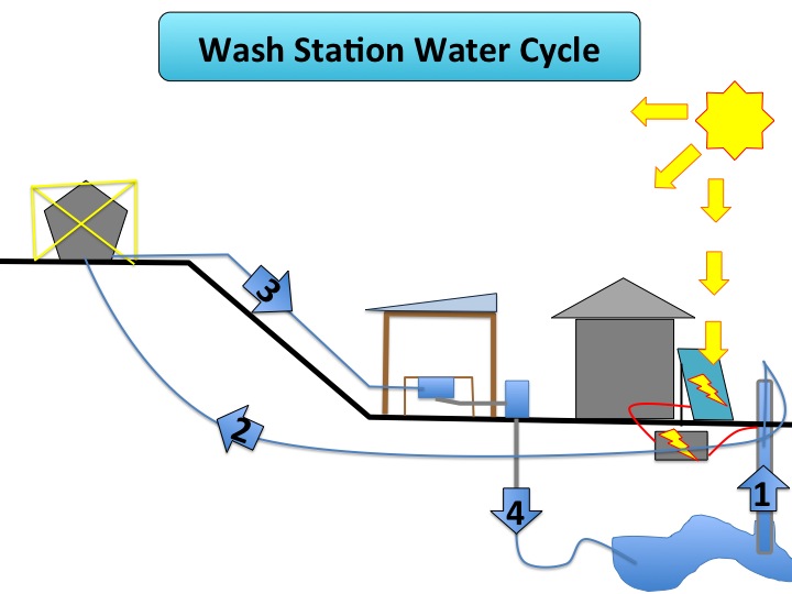
- Step 1: Water is pumped up from a well using a solar powered water pump that also get sanitized through a solar powered UV-filter.
- Step 2: Water continues to pump vertically up to a water collection container.
- Step 3: Water is gravity fed downhill to be used both on the LaFarm’s commercial and communal plots as well as at the wash station adjacent to the tool shed and solar-pv panels.
- Step 4: After having been used at the wash station, water is gravity fed through a PVC installed plumbing system into a collection barrel. The water is tested to ensure that it is safe enough to be properly released back into the environment.
Now that we have looked at the wash station and the structure that will enclose it, we must look at our water source, how it works, and how it will be powered. As the name of the project suggests, our energy will come from solar panels. These panels already power a water pump, but with our project we will add a UV filter to the system. After the filter is added to the existing gravity-powered system, we will connect our wash station to complete the system.
The UV filter will replace the current method of water purification (which entails the use of bleach poured directly into the well). The UV filter will be placed right after the pump, so that purified water is pumped up the hill into the reservoir. Placing it near the pump will minimize the amount of extra circuitry that will need to be included, since the pump is already powered by the solar panels. Due to the extra demands the UV filter will place on the electrical system, a deep-cycle battery will be installed between the solar panels and the pump/UV filter to ensure the system can operated all day with the stored capacity.
In regards to selecting a UV water filter and battery, our group would refer the civil engineering construction team to Viqua in order to select a model that is compatible with the flow rate of the existing water pump. We faced difficulties in calculating the necessary flow rate because the current pump is submerged.The link to the UV filter producer can be found here: (http://viqua.com/help-me-choose/)
Similarly, the deep cycle battery’s price can varies based on the capacity needed. Hence, once the UV filter is selected. We recommend the implementation team to further analyze the power input for both the UV filter as well as the irrigation system and select the desired battery capacity. The link to a battery producer can be found here: (http://www.wholesalesolar.com/)
We hope that by using materials that are durable yet affordable, and by ensuring the wash station functions as an integral mechanism in the overall process at LaFarm, our design will fulfill the needs of the farm as it grows and develops for years to come.