 |
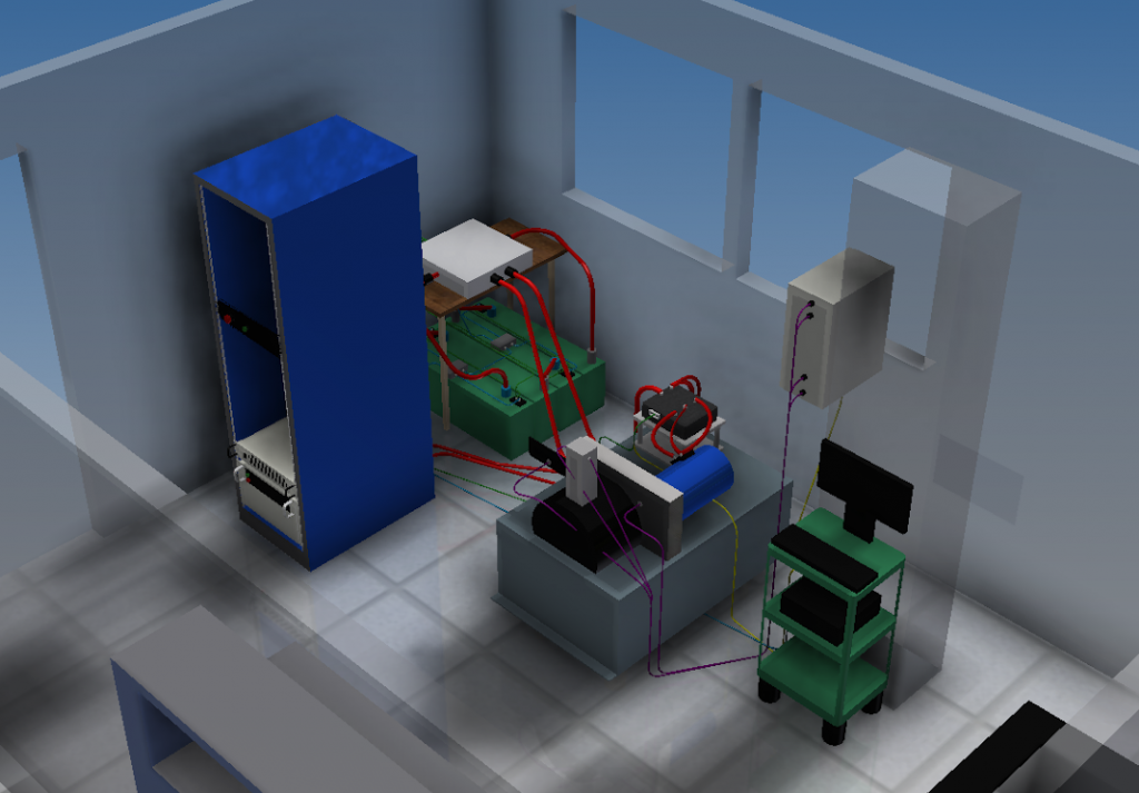
| A computer generated image of the Dynamometer room, AEC 401 |
This page documents the design efforts accomplished during the Spring 2015 semester. The system was successfully delivered, consisting of an: electric motor, high voltage power supply, cooling system, and data acquisition software.
Project Documentation
Listed below is documentation for all of the systems designed by the DYNO group.
- LFEV Dynamometer Final System Design
- LFEV Dynamometer Maintenance Manual
- LFEV Dynamometer Software/CAN Interface
Huff Documentation
Listed below is the documentation provided with the Huff Dynamometer Box.
- Huff Oil Valve (CAT HY14-3200)
- Huff Box Layout (1/2) (ISO-RACK08)
- Huff Box Layout (2/2) (SSR-RACK08)
- Load Cell (LCCE)
- Strain Gauge Acquisition Card (SCM5B38N)
- Tachometer Acquisition Card (SCM5B45)
- Throttle Voltage Output Card (SCM5B49)
- MCDAQ USB-7000 Series Datasheet
- MCDAQ USB-7204 User Manual
Project Deliverables
PDR Deliverables
D000 – Preliminary Design Report
D004 – Acceptance Test Plan – Outline
PDR Presentation
D004 – Acceptance Test Plan – Draft
Updated Work Breakdown Schedule
D002 – Dyno User Manual
QA Tests
QA Test- 4/23
QA Test 1 – 4/30
QA Test 2 – 4/30
QA Test 3 – 4/30
QA Test 4 – 4/30
QA Test – 5/8 – 10 HP Temp Rise Test
Inspection Report
Inspection Report
ATP Tests
PDF | CSV
10 HP Test | 10 HP Test
50 sweep | 50 sweep
60 – 0 sweep | 60 – 0 sweep
100 sweep | 100 sweep
sweep | sweep
Test 1 | Test 1
Test 2 | Test 2
Test 3 | Test 3
Calibration
RPM Calibration Data
Torque Calibration Data
T001-2 Analysis
D011 – Dyno Calibration and Accuracy
Acceptance Test Report
D004 – Acceptance Test Plan
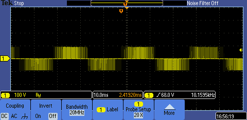
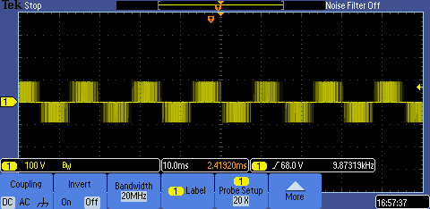
| Motor Scope Shots | |
| 2000 RPM High Load | 2000 RPM Low Load |
 |
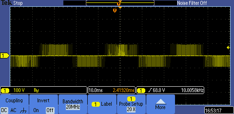 |
| 2000 RPM High Load | 2000 RPM Low Load |
 |
 |
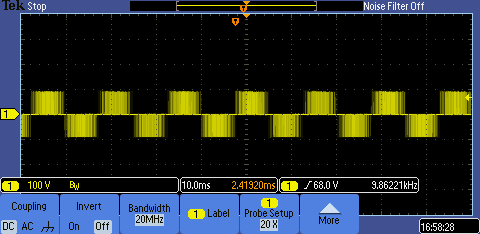
| 3000 RPM High Load | 3000 RPM Low Load |
 |
 |